Eureka AIR delivers breakthrough ideas for toughest innovation challenges, trusted by R&D personnel around the world.

Driver monitoring device mounting structure

Active Publication Date: 2020-05-21
TOYOTA JIDOSHA KK
View PDF0 Cites 1 Cited by
  • Summary
  • Abstract
  • Description
  • Claims
  • Application Information

AI Technical Summary

Benefits of technology

This disclosure is about a device that attaches a driver monitoring device to a steering column. The device includes a supporting component that holds a connector that connects to a lead wire coming from the monitoring device. A cover is also provided that attaches to the steering column and provides temporary and permanent fixation for the monitoring device. The technical effects of this device include improved stability and security for driver monitoring and simplified installation process.

Problems solved by technology

However, because the lead wire for the video signal output has an internal metal shielding component for reducing noise, the lead wire is extremely rigid (i.e., stiff), and when curving the lead wire in order to lead it to the fixing portion of the column cover, it is difficult to stabilize the position of the bracket because of the reaction force from the lead wire.
In other words, it is difficult to fix the bracket onto the fixing portion or the like of the column cover.

Method used


Image

  • Driver monitoring device mounting structure
  • Driver monitoring device mounting structure
  • Driver monitoring device mounting structure

Examples


Embodiment Construction

[0015]Hereinafter, an exemplary embodiment for implementing the present disclosure will be described in detail with reference to the drawings. Note that an arrow UP, an arrow RE, and an arrow RH that are shown in the appropriate drawings respectively indicate a vehicle upward direction, a vehicle rearward direction, and a right side in a vehicle width direction. Accordingly, if front-rear, left-right, or up-down directions are used in the following description, then, unless specifically stated otherwise, these refer respectively to the front-rear directions of the vehicle, the left-right directions of the vehicle (i.e., the vehicle width direction), and the up-down directions of the vehicle.

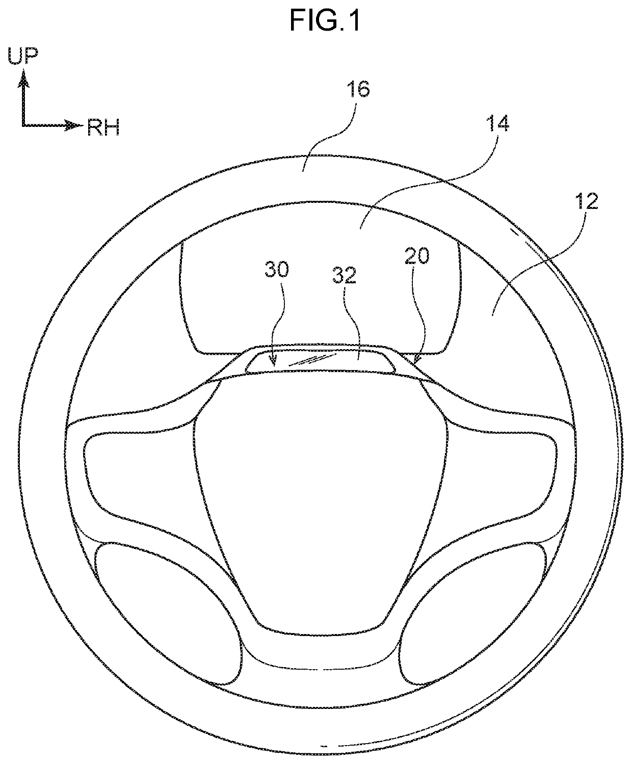
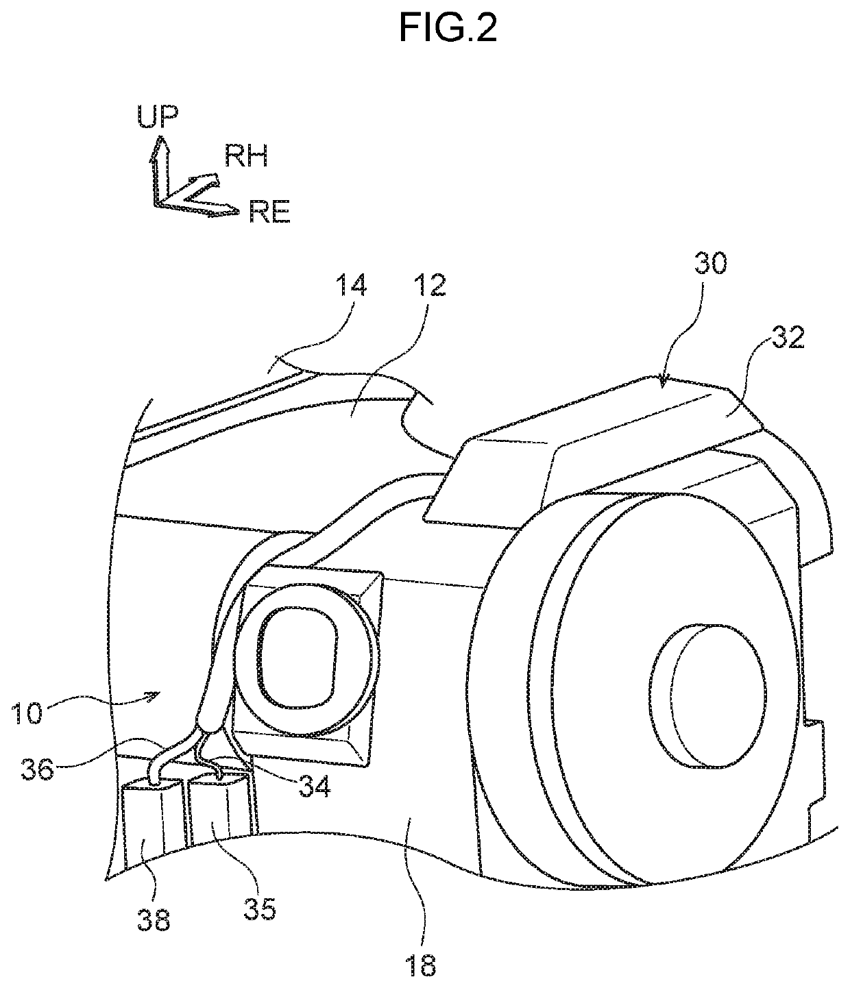
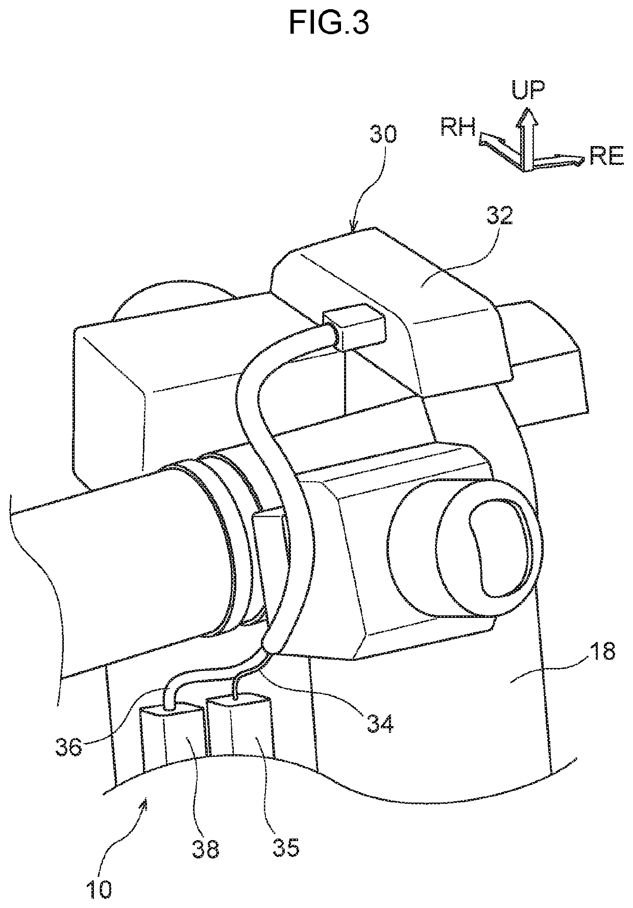
[0016]As is shown in FIG. 1 through FIG. 3, a display unit 14 on which various meter instruments such as a speedometer and the like are displayed is disposed in an instrument panel 12 on a vehicle front side of a steering wheel 16. In addition, a camera main body 32 of a driver monitoring camera ...


PUM


Abstract

A driver monitoring device mounting structure that includes: a driver monitoring device main body that is attached to a steering column; a supporting component that has an anchoring portion and a fastening portion, and that supports a connector that is attached to a lead wire that is drawn out from the driver monitoring device main body; and a column cover that has a temporary fixing portion to which the anchoring portion is temporarily fixed, and a fixing portion to which the fastening portion is fixed, and that covers the steering column.

Description

CROSS-REFERENCE TO RELATED APPLICATION[0001]This application is based on and claims priority under 35 USC 119 from Japanese Patent Application No. 2018-216683 filed on Nov. 19, 2018, the disclosure of which is incorporated by reference herein.BACKGROUNDTechnical Field[0002]The present disclosure relates to a mounting structure for a driver monitoring device.Related Art[0003]In order to monitor the orientation of the face of a driver while this driver is driving a vehicle (for example, to check whether the driver is distracted or is becoming drowsy), a structure exists in which a driver monitoring camera is provided in an upper portion of a steering column (see, for example, Japanese Unexamined Patent Application (JP-A) No. 2011-154721).[0004]Normally, various types of meters are disposed within the line of sight of a driver. Accordingly, if a driver monitoring camera (i.e., a driver monitoring device main body) is mounted on an upper portion of a steering column, in order to ensure ...

Claims


Application Information

Patent Timeline
IPC IPC(8): A61B5/00B60R16/023B60R11/04G06K9/00H04N5/225
CPCB60R16/023A61B5/6893A61B5/18H04N5/2253A61B5/0077G06K9/00845B60R2011/001B60R11/04G06V20/597H04N23/57H04N23/54
Inventor TAKAI, YUSUKE
Owner TOYOTA JIDOSHA KK
Why Eureka
Eureka Blog
Learn More