Control device for differential limiting device

Inactive Publication Date: 2020-05-21
JTEKT CORP
View PDF0 Cites 0 Cited by
  • Summary
  • Abstract
  • Description
  • Claims
  • Application Information

AI Technical Summary

Benefits of technology

This patent describes a control device for a differential limiting device that improves the stability of a vehicle when it is subjected to crosswinds. By controlling the device before the vehicle is exposed to wind, the device can prevent the vehicle from becoming unstable and potentially dangerous on the road.

Problems solved by technology

Accordingly, when the vehicle is subjected to a crosswind during driving, the vehicle behavior becomes temporarily unstable, which may make the driver feel uneasy.

Method used


Image

  • Control device for differential limiting device
  • Control device for differential limiting device
  • Control device for differential limiting device

Examples


Embodiment Construction

[0019]A first embodiment of the disclosure will be described with reference to FIGS. 1 to 5. Embodiments described below are given as specific examples for carrying out the disclosure. However, the technical scope of the disclosure is not limited to these specific forms.

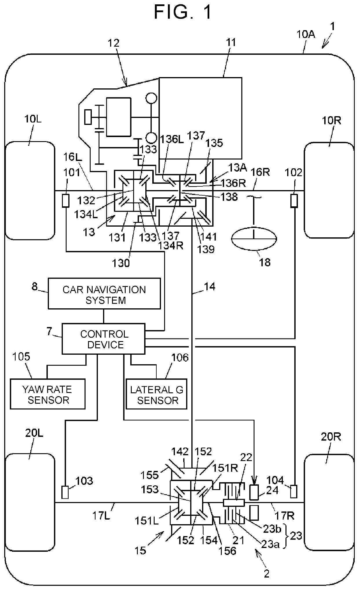
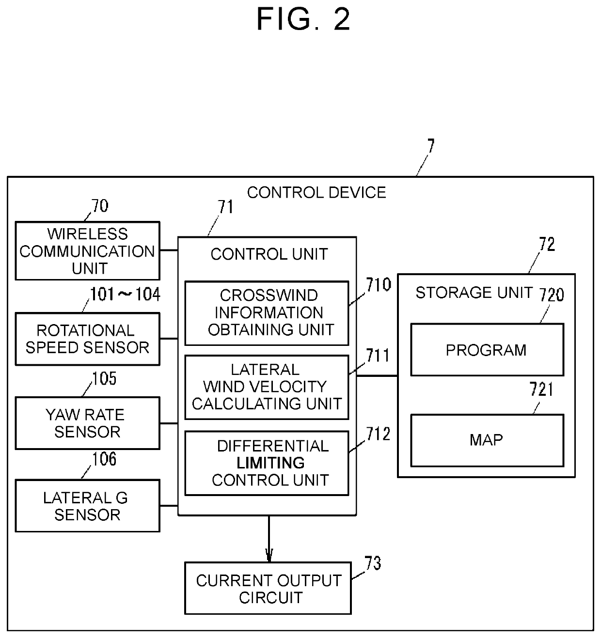
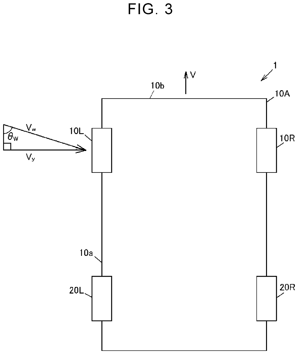
[0020]FIG. 1 is a configuration diagram schematically illustrating an example of the configuration of a four-wheel drive vehicle including a differential limiting device according to the first embodiment of the disclosure. FIG. 2 is a block diagram illustrating an example of a functional configuration of a control device. FIG. 3 is a schematic illustration of a vehicle that is subjected to a crosswind. FIGS. 4A and 4B are schematic illustrations of the vehicle near a tunnel exit. FIG. 5 is a flowchart illustrating an example of a process that is executed by a control unit of a control device.

[0021]As shown in FIG. 1, a four-wheel drive vehicle 1 includes an engine 11, a transmission 12, front wheels 10R, 10L, and rea...


PUM


Abstract

A control device for a differential limiting device is provided. The differential limiting device limits at least one of a difference between rotational speeds of right and left wheels of a vehicle and a difference between rotational speeds of front and rear wheels of the vehicle. The control device includes an electronic control unit configured to obtain crosswind information on a crosswind to which the vehicle is to be subjected in a predetermined region located ahead in a direction of travel of the vehicle, and to perform control to generate a differential limiting force based on the crosswind information.

Description

INCORPORATION BY REFERENCE[0001]The disclosure of Japanese Patent Application No. 2018-218063 filed on Nov. 21, 2018 including the specification, drawings and abstract is incorporated herein by reference in its entirety.BACKGROUND1. Technical Field[0002]The disclosure relates to a control device for a differential limiting device that limits at least one of the difference between rotational speeds of front and rear wheels and the difference between rotational speeds of right and left wheels.2. Description of Related Art[0003]A differential limiting force control device has been proposed. The differential limiting force control device limits the differential between right and left wheels to restrain undesirable movement of a vehicle toward the right side or the left side caused by disturbance during traveling (see, for example, Japanese Unexamined Patent Application Publication No. 2009-257383 (JP 2009-257383 A)).[0004]The differential limiting force control device described in JP 20...

Claims


Application Information

Patent Timeline
IPC IPC(8): B60K23/04B60K17/346B60W10/119
CPCB60K17/3462B60W2520/28B60W10/119B60K23/04B60K17/165B60K17/346B60W30/02F16H48/12G08G1/0967B60K23/0808B60K2023/043B60K2023/0816B60K2023/0858B60W50/0097B60W2556/50
Inventor TAKAUE, HIROTO
Owner JTEKT CORP
Why Eureka
Try Eureka