Gas sensor fault detection device, gas sensor fault detection system, and gas sensor fault detection method
- Summary
- Abstract
- Description
- Claims
- Application Information
AI Technical Summary
Benefits of technology
Problems solved by technology
Method used
Image


Examples
first embodiment
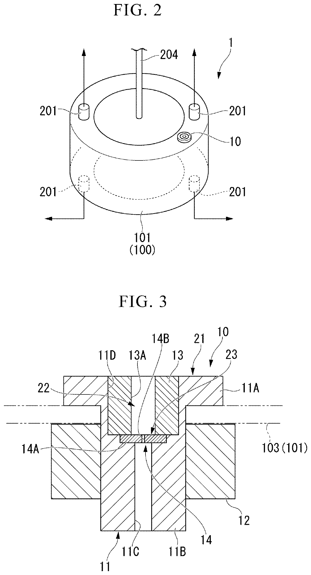
[0017]Hereunder, a first embodiment of the present invention will be described with reference to FIG. 1 and FIG. 2. In the following drawings, the thicknesses and dimensional ratios of the components are adjusted to make the drawings easier to see. In particular, in FIG. 3, the orifice section is drawn considerably larger than the actual dimensional ratio in order to make the orifice easier to see.
[0018]The gas sensor fault detection device of the first embodiment is a device that detects a fault in a gas sensor of a gas leak inspection device. The gas leak inspection device is a device that detects whether or not a gas leak has occurred from an inspection target, such as a tire. Therefore, before describing the gas sensor fault detection device, the configuration of the gas leak inspection device will be firstly described.
[0019]In the gas leak inspection device, the inspection target representing the gas leak inspection target is arbitrary. As shown in FIG. 1, the inspection target...
second embodiment
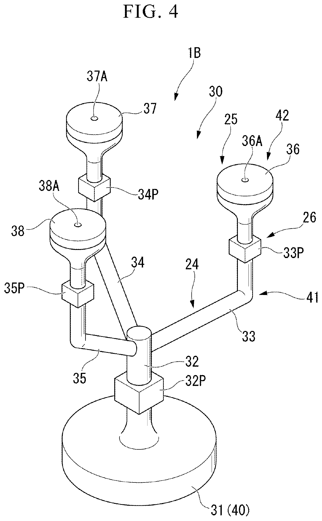
[0060]Next, a second embodiment of the present invention will be described with reference to FIG. 4. A gas sensor fault detection device 1B of the second embodiment replaces the configuration in which the installation jig 10 is installed on the tire 101, with the trace gas blowing device 30 shown in FIG. 4.
[0061]As shown in FIG. 4, the trace gas blowing device 30 includes a support 40. The support 40 is configured by a base 31. The base 31 has a disk shape, and is capable of being mounted, for example, on the rotation driver 202A of the gas leak inspection device 200 shown in FIG. 1. The support 40 does not have to be the base 31. For example, the support 40 may be, in addition to a member that is mounted on the rotation driver 202A, a member or the like that is fixed to the rotation driver 202A, or another position.
[0062]The gas sensor fault detection device 1B includes a position fixing unit 24, a gas blowing unit 25, and a blowing amount adjustment unit 26. The position fixing un...
third embodiment
[0071]Next, a third embodiment of the present invention will be described with reference to FIG. 5A to 5C. As with the gas sensor fault detection device 1B of the second embodiment, a gas sensor fault detection device 1C of the third embodiment replaces the configuration in which the installation jig 10 is installed on the tire 101, with the trace gas blowing device 50 shown in FIG. 5A to 5C.
[0072]As shown in FIG. 5A, the trace gas blowing device 50 includes a support 60. The support 60 is configured by a base 51. The base 51 has a disk shape, and is capable of being mounted, for example, on the rotation driver 202A of the gas leak inspection device 200 shown in FIG. 1. The support 60 does not have to be the base 51. For example, in addition to a member that is mounted on the rotation driver 202A, it may be a member or the like that is fixed to the rotation driver 202A, or another position.
[0073]The gas sensor fault detection device 1C includes a position fixing unit 27, a gas blowi...
PUM
 Abstract
Description
Claims
Application Information
 - R&D
- Intellectual Property
- Life Sciences
- Materials
- Tech Scout
- Unparalleled Data Quality
- Higher Quality Content
- 60% Fewer Hallucinations
Browse by: Latest US Patents, China's latest patents, Technical Efficacy Thesaurus, Application Domain, Technology Topic, Popular Technical Reports.
© 2025 PatSnap. All rights reserved.Legal|Privacy policy|Modern Slavery Act Transparency Statement|Sitemap|About US| Contact US: help@patsnap.com