
Dental traction device

a technology of traction device and traction body, which is applied in dental surgery, othrodontics, medical science, etc., can solve the problems of easy loosening of the rope body, high cost, and easy loosening of the rubber band, and achieves convenient use, avoid falling off, and easy and rapid traction.

Inactive Publication Date: 2020-05-28
CHEN YI WEN +1
View PDF5 Cites 4 Cited by
  • Summary
  • Abstract
  • Description
  • Claims
  • Application Information

AI Technical Summary

Benefits of technology

The present invention is a dental traction device that can correct dental corrections without being expensive or difficult to use. The device includes a seat-body, an elastic element, and a tractive-body that works with a blocking-stopping-body to prevent slipping, loosening, and falling-off. The elastic element creates a pulling force that is directed towards the bone nail, extension main-body, and dental orthotics, resulting in effective traction correction. This device offers practicality and progressiveness, avoiding the troubles of expensive and difficult-to-use conventional tractors.

Problems solved by technology

However, sometimes the teeth may be skewed or the spacing is too large, so that just using the traditional orthotic cooperating with the rope body to pull is not enough to correct; therefore the traditional tractor cooperating with the rubber band is added to adjust; but the traditional tractor has the defect which the rope body is easy to be loosen; therefore the industry has improved to develop the conventional tractor.
However, the round-hook-body needs to be set in parallel with the teeth, and the opening needs to face away from the side of the rubber band to keep the rubber band from falling off; if the round-hook-body forms an angle with the teeth or the opening faces the rubber band, the rubber band is likely to fall off; therefore, it is necessary to make two styles, the left-hook and the right-hook; in addition to being more expensive, it is more troublesome to use.

Method used


Image

  • Dental traction device
  • Dental traction device
  • Dental traction device

Examples


Embodiment Construction

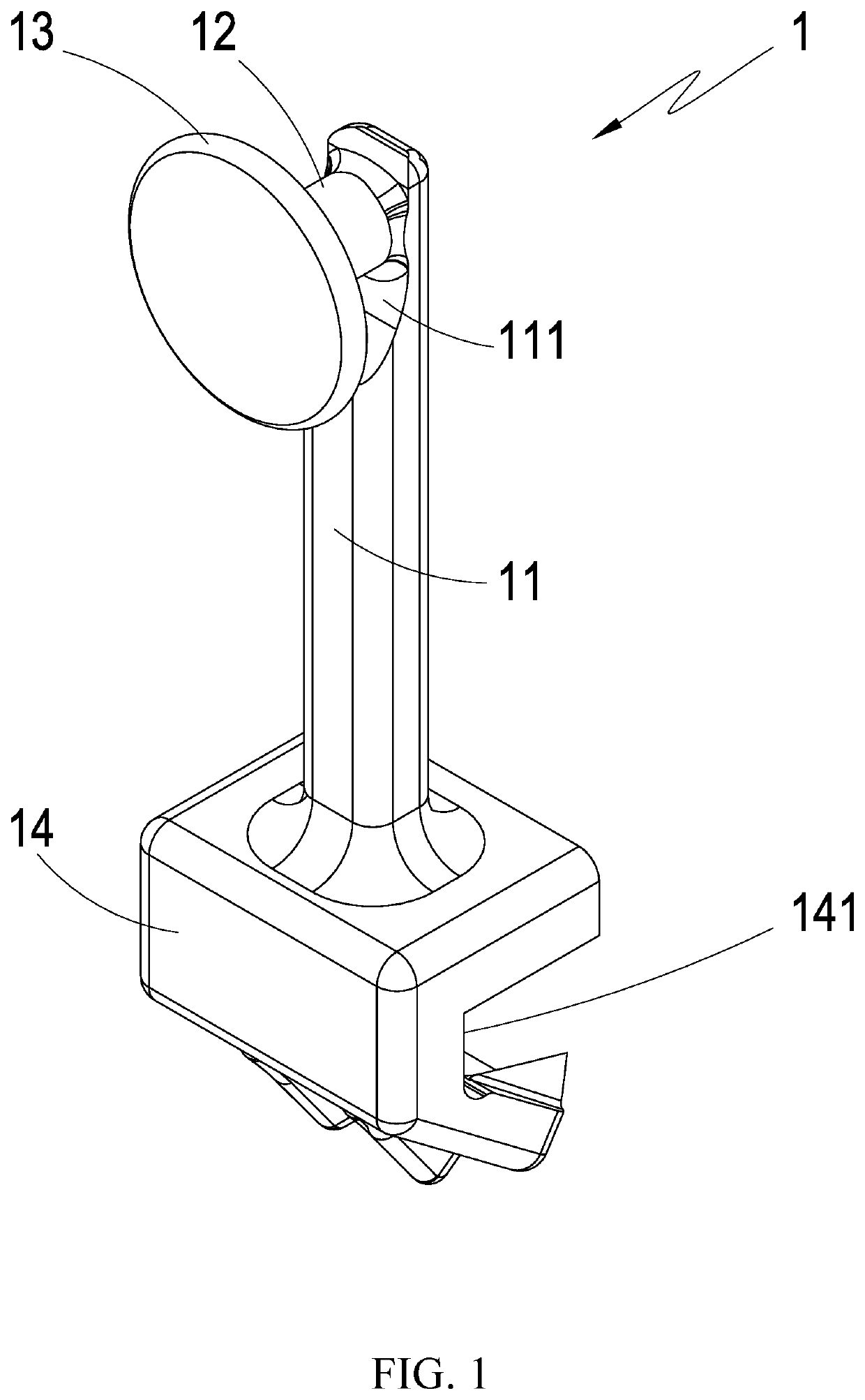
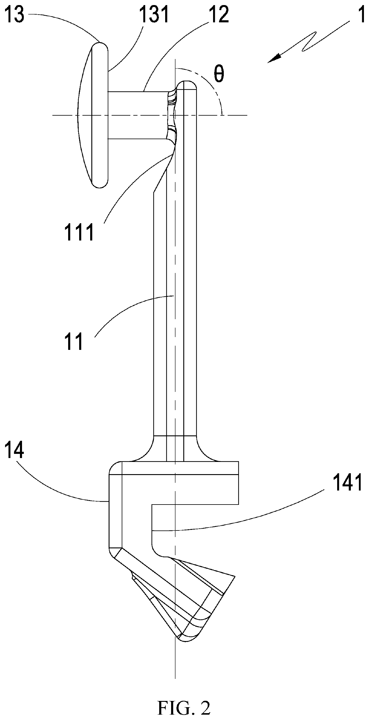
[0018]The following descriptions are exemplary embodiments only, and are not intended to limit the scope, applicability or configuration of the invention in any way. Rather, the following detailed description provides a convenient illustration for implementing exemplary embodiments of the invention. Various changes to the described embodiments may be made in the function and arrangement of the elements described without departing from the scope of the invention as set forth in the appended claims.

[0019]The foregoing and other aspects, features, and utilities of the present invention will be best understood from the following detailed description of the preferred embodiments when read in conjunction with the accompanying drawings.

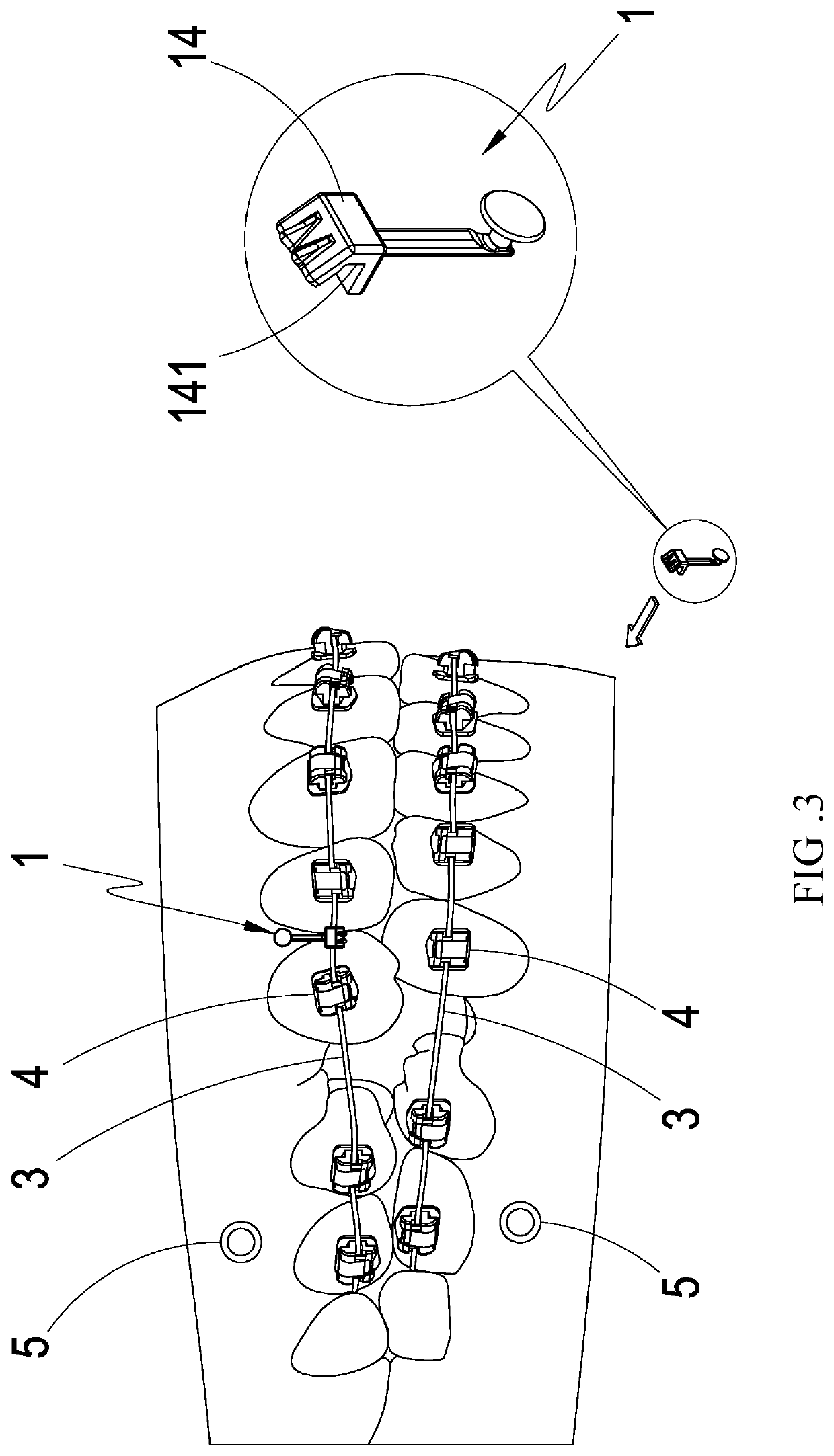
[0020]Please refer to FIG. 1 and FIG. 2, which are the stereoscopic schematic diagram and the side-view schematic diagram of the preferred embodiment of the present invention; it can be clearly seen from the figures that the dental traction device 1 of the p...


PUM


Abstract

A dental traction device comprises an extension main-body, a tractive-body, a blocking-stopping-body, and a seat-body. When using, the dental orthotics are firstly set and the dental correction archwire connection is set, and the bone nail is set at the gum; then, the seat-body is fixed on the dental correction archwire; one end of the elastic element is bypass the blocking-stopping-body to stick and engage on the tractive-body and the other end is stuck and engaged on the bone nail; then the blocking-stopping-body is cooperated with the tractive-body to fix the elastic element to avoid falling-off; and the contraction elastic force of the elastic element generates the pulling force to the dental correction archwire and the teeth by using the extension main-body as the force moment to produce the traction correction effect; and so as to achieve the practicality and progressiveness which is convenient in use and avoids falling-off.

Description

(A) TECHNICAL FIELD OF THE INVENTION[0001]The present invention provides a dental traction device, and especially relates to a dental traction device which is convenient in use and avoids falling-off.(B) DESCRIPTION OF THE PRIOR ART[0002]Generally, teeth can be regarded as a person's facade; when everyone talks to each other, if they see a pair of disorganized teeth, they will have an impact on people's first impression, and the first impression between people will often determine many key points. Therefore, modern people care about the care and cleanliness of their teeth.[0003]The most common way to adjust the position and shape of teeth is to wear braces; where the braces are also divided into many kinds, and the more popular way is to use the traditional orthotic cooperating with the rope body to pull to gradually change the position of the teeth.[0004]However, sometimes the teeth may be skewed or the spacing is too large, so that just using the traditional orthotic cooperating w...

Claims


Application Information

Patent Timeline
Patent Type & Authority Applications(United States)
IPC IPC(8): A61C7/22
CPCA61C7/22A61C7/36A61C8/0096
Inventor CHEN, YI-WENLIN, HSI-YUANCHIU, HAO-MING
Owner CHEN YI WEN
Learn More