Light path adjustment mechanism

a light path and adjustment mechanism technology, applied in the field of optical mechanisms, can solve the problems of difficult miniaturization of the entire mechanism, large number of components, weight and occupied space of the conventional light path adjustment mechanism, etc., and achieve the effects of eliminating dark regions, improving picture quality, and improving image resolution

Active Publication Date: 2020-06-04
YOUNG OPTICS
View PDF1 Cites 1 Cited by
  • Summary
  • Abstract
  • Description
  • Claims
  • Application Information

AI Technical Summary

Benefits of technology

[0006]According to the above aspects, the light path adjustment mechanism may modify or change light paths to enhance image resolution, improve picture quality (e.g., eliminating dark regions or blurring image edges), or provide other beneficial effects. Moreover, the optical plate member is allowed to tilt about two distinct axes to four different positions simply by disposing two actuators on two adjacent sides (or two adjacent middle areas), which relies on the interaction between acting forces of the actuators and resilient forces of the elastic members to cause reciprocating motion of the carrier. This allows to reduce occupied space, weight and component number. Further, the elastic member may have multiple sections extending in different directions to, for example, reduce the resistance for tilting or rotating motions.

Problems solved by technology

However, the number of components, weight and occupied space of a conventional light path adjustment mechanism is considerably large, and thus the entire mechanism is difficult to be miniaturized.

Method used


Image

  • Light path adjustment mechanism
  • Light path adjustment mechanism
  • Light path adjustment mechanism

Examples


Embodiment Construction

[0022]In the following detailed description of the preferred embodiments, directional terminology, such as “top,”“bottom,”“front,”“back,” etc., is used with reference to the orientation of the Figure(s) being described. The components of the invention can be positioned in a number of different orientations. As such, the directional terminology is used for purposes of illustration and is in no way limiting. Further, “First,”“Second,” etc, as used herein, are used as labels for nouns that they precede, and do not imply any type of ordering (e.g., spatial, temporal, logical, etc.).

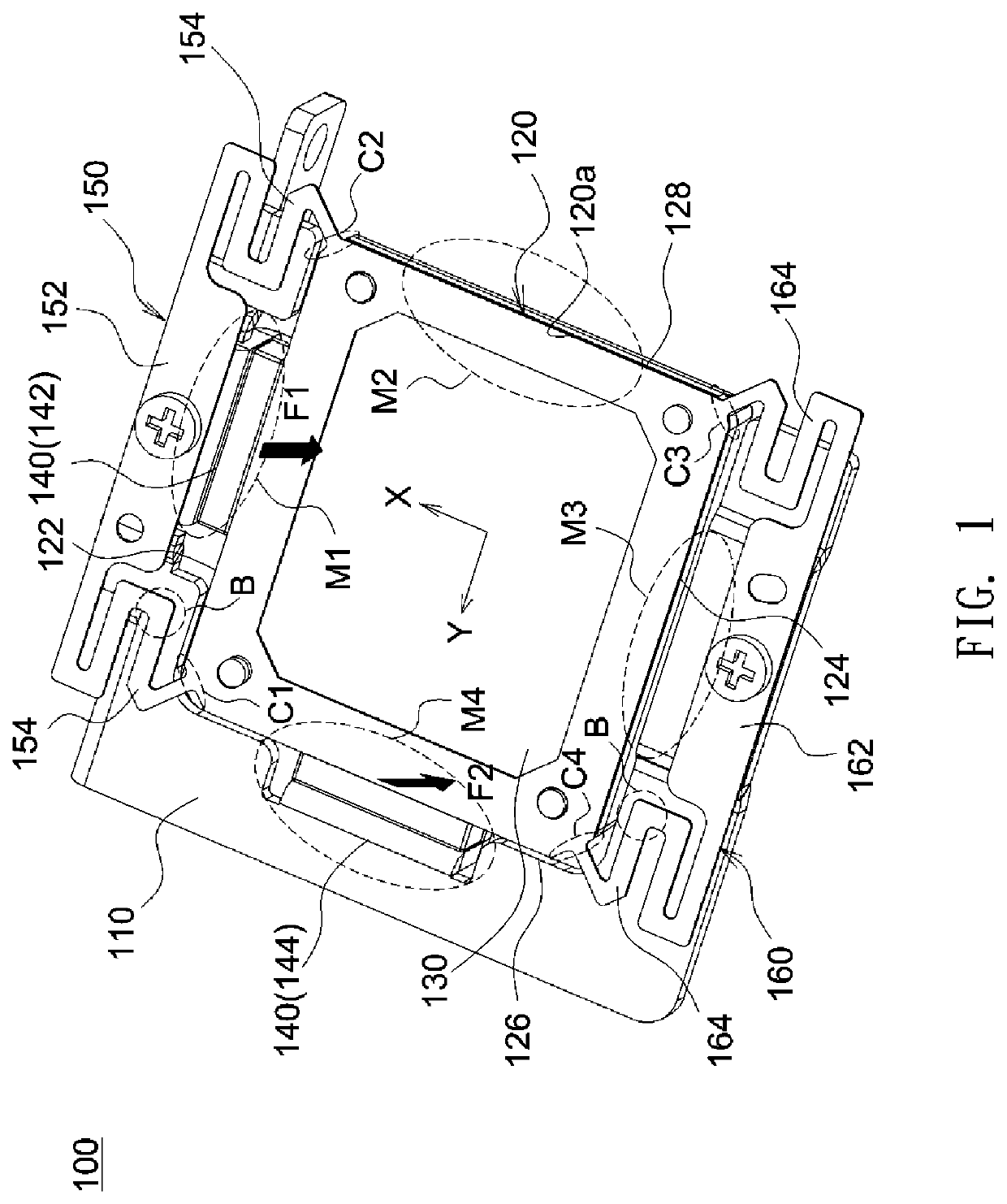
[0023]The following description relates in general to a light path adjustment mechanism used with an optical system (e.g., a display device or a projector) to modify or change light paths to enhance perceived image resolution, improve picture quality (e.g., eliminating dark regions or blurring image edges), or provide other beneficial effects. Further, it should be understood that the light path adjustment me...


PUM

PropertyMeasurementUnit
areaaaaaaaaaaa
distanceaaaaaaaaaa
flexibleaaaaaaaaaa

Abstract

A light path adjustment mechanism includes a support, a carrier, an optical plate member and a plurality of actuators. The carrier is disposed on the support and connected to the support via a first elastic member and a second elastic member. The carrier includes a first side, a second side opposite the first side, a third side and a fourth side opposite the third side, and each of the third side and the fourth side is located between the first side and the second side. The actuators are disposed on at most three sides of the first side, the second side, the third side and the fourth side, and the actuators are disposed at least on the first side and the third side.

Description

BACKGROUND OF THE INVENTIONa. Field of the Invention[0001]The invention relates generally to an optical mechanism, and more particularly to a light path adjustment mechanism.b. Description of the Related Art[0002]Nowadays, various image display technologies are widely used in daily life. In order to increase the resolution and picture quality of an image display device, a light path adjustment mechanism can be used to adjust propagation paths of light in the image display device to shift pixel images and thereby increase addressability. However, the number of components, weight and occupied space of a conventional light path adjustment mechanism is considerably large, and thus the entire mechanism is difficult to be miniaturized. Therefore, it is desirable to provide a simple, reliable, light and compact design of a light path adjustment mechanism.BRIEF SUMMARY OF THE INVENTION[0003]According to one aspect of the present disclosure, a light path adjustment mechanism includes a suppo...

Claims


Application Information

Patent Timeline
Patent Type & Authority Applications(United States)
IPC IPC(8): G02B26/08G02B7/02G02B7/182H01F7/02
CPCG02B26/085G03B2205/0069G02B7/182G02B7/02H01F7/02G02B26/0875H01F7/14H01F7/122
Inventor LIN, WEI-SZU
Owner YOUNG OPTICS
Why Eureka
Try Eureka