Supporting element for tobacco industry machine

a technology of supporting elements and tobacco industry, which is applied in the direction of metal working apparatus, tobacco, food science, etc., can solve the problems of unfulfilled adhesives, and achieve the effect of improving cutting quality and increasing tobacco quality

Inactive Publication Date: 2020-06-11
INT TOBACCO MACHINERY POLAND
View PDF0 Cites 0 Cited by
  • Summary
  • Abstract
  • Description
  • Claims
  • Application Information

AI Technical Summary

Benefits of technology

[0012]An advantage of the solution according to the invention is an increased quality of the tobacco, filter or multi-segment rods, in particular an improved cutting quality. The application of depression according to the invention forms a removing channel which allows removing adhesive or other dirt generated in the course of production of the continuous rod or in the process of knife sharpening. As a result, such dirt does not get into a receiving sleeve and does not cause product degradation.

Problems solved by technology

During cutting of such a continuous rod, it may happen that the adhesive has not fully set i.e. dried in the case of the PVA adhesive or cooled in the case of “hot melt” adhesive.

Method used


Image

  • Supporting element for tobacco industry machine
  • Supporting element for tobacco industry machine
  • Supporting element for tobacco industry machine

Examples


Embodiment Construction

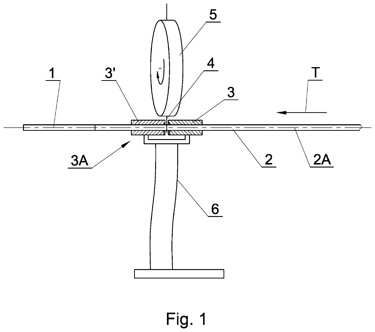
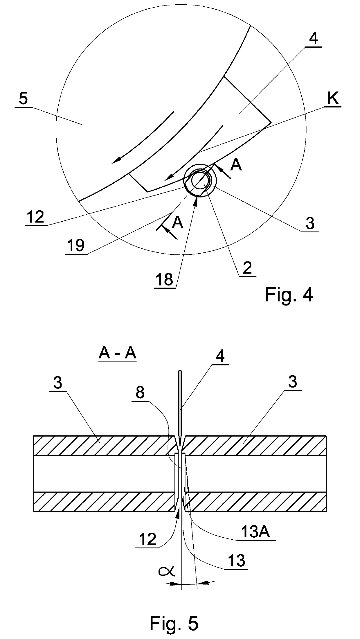
[0023]FIG. 1 shows a fragment of a machine for manufacturing rods 1 of a continuous rod 2 moving axially and lengthwise. The continuous rod 2 is conveyed in the direction T shown with the arrow and moves through cutting sleeves 3, 3′ which are mechanically connected with each other and constitute a supporting unit 3A designed to support the continuous rod 2 during cutting. The cutting sleeves 3, 3′ may be identical. The sleeves 3, 3′ may be mounted to flexible springy elements 6 or in any other way typical for rod manufacturing machines of the tobacco industry. A drive mechanism designed to put the sleeves 3, 3′ into reciprocating motion in the direction of movement of the continuous rod 2 is not shown in the drawing. The cutting sleeves and other elements fulfilling the same function will be hereinafter referred to as supporting elements.

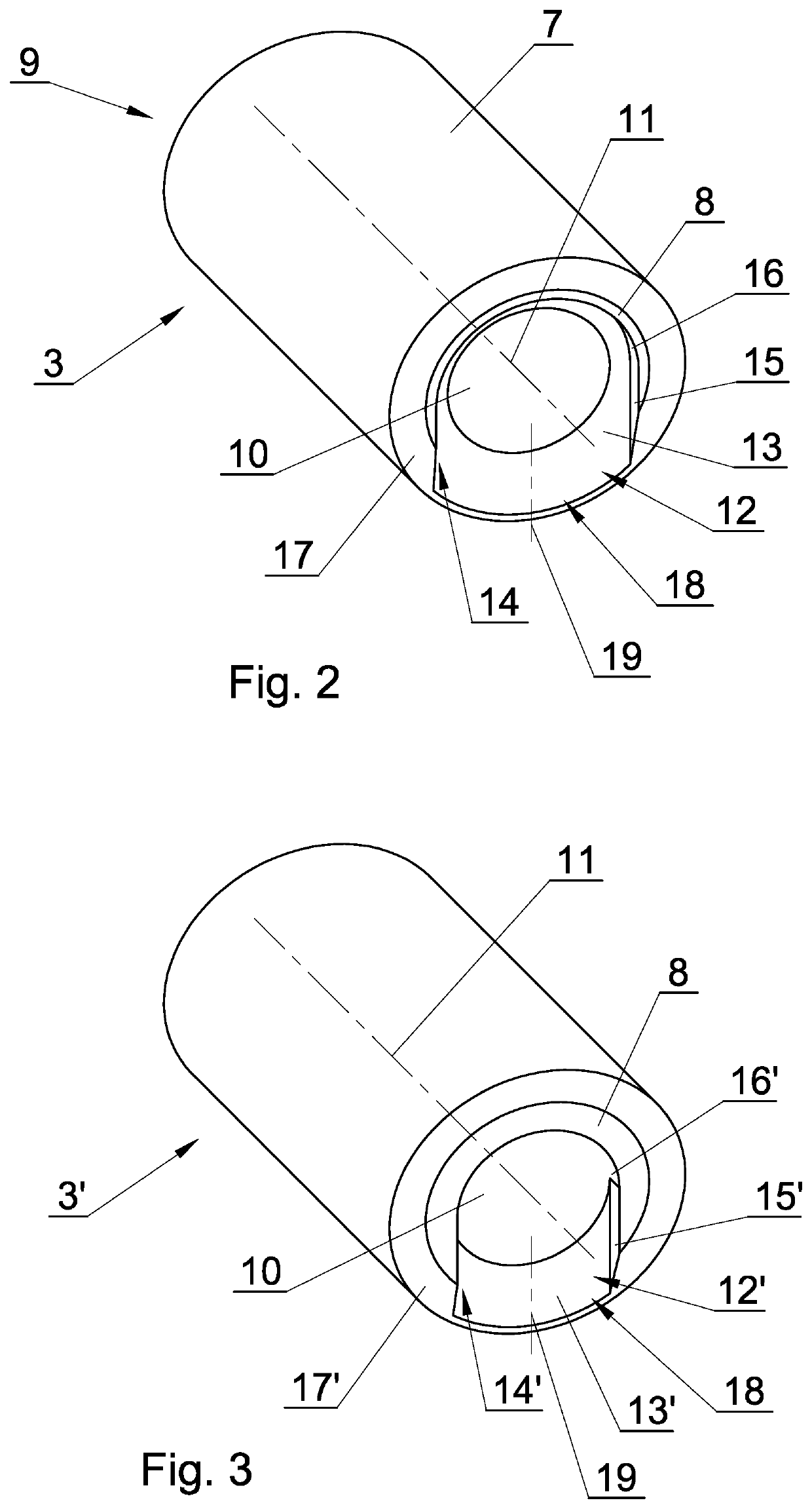
[0024]The supporting element 3 shown in FIG. 2 has a cylindrical outer surface 7 and two front surfaces 8 and 9. The supporting element 3 has a su...


PUM


Abstract

The object of the application is a supporting element (3, 3′, 33) for a tobacco industry machine designed to support a continuous rod, moving axially (2) during cutting by a rotationally mounted knife (4), whereas the supporting element (3, 3′, 33) comprises an at least partially cylindrical supporting surface (10) for the continuous rod (2), having a longitudinal axis (11), moreover the supporting element (3, 3′, 33) has a front surface (8) constituting a cutting surface, characterised in that the front surface (8) has a depression (12, 12′, 42).

Description

BACKGROUND[0001]The object of the invention is a supporting element for a tobacco industry machine used in a production machine for manufacturing tobacco, filter or multi-segment rods.[0002]In the machines for manufacturing tobacco or filter rods of a defined length, first a continuous rod is manufactured which is cut during its movement into individual rods cut off from the continuous rod. Originally, reciprocating mounted knives situated perpendicular to the axis of the manufactured continuous rod were used. Presently, rotating knives which cut the continuous rod during the movement of the rod are commonly used. The rotating knives are mounted to a rotating knife head whose axis is not parallel to the axis of the continuous rod. The inclination of the knife head and the special mounting of the knives make it possible to cut the continuous rod during movement. An element for supporting the continuous rod during the cutting is required in order to cut of the continuous rod, usually ...

Claims


Application Information

Patent Timeline
Patent Type & Authority Applications(United States)
IPC IPC(8): A24C5/28A24C5/00A24C5/39
CPCA24C5/39A24C5/002A24C5/28B26D1/56A24C5/00A24D3/0254
Inventor CIESLIKOWSKI, BARTOSZFIGARSKI, RADOSLAW
Owner INT TOBACCO MACHINERY POLAND
Why Eureka
Try Eureka