
Compliant anvil

a technology of anvil and abrasives, applied in mechanical work/deformation, printing, other domestic articles, etc., can solve the problems of knife deformation, knife deformation, knife localization, and often multi-directional deformation

Active Publication Date: 2020-06-11
THE PROCTER & GAMBLE COMPANY
View PDF0 Cites 0 Cited by
  • Summary
  • Abstract
  • Description
  • Claims
  • Application Information

AI Technical Summary

Benefits of technology

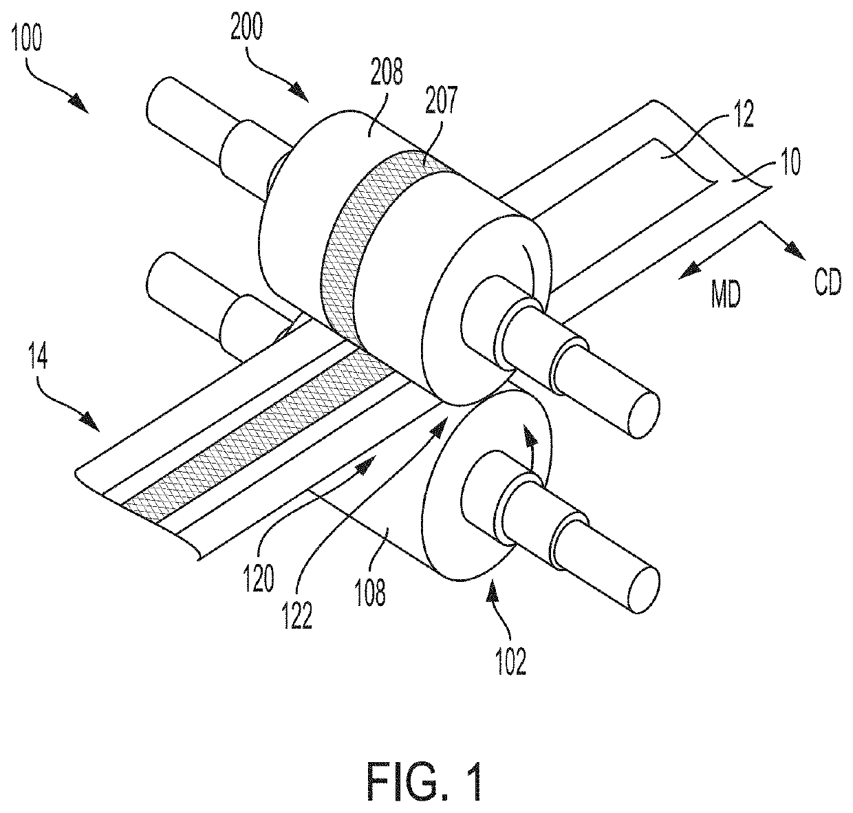
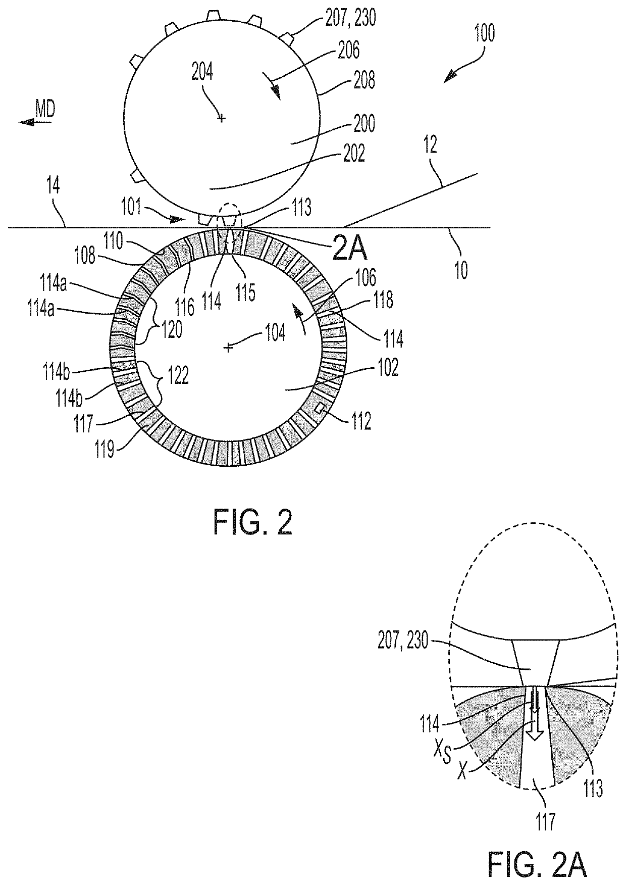
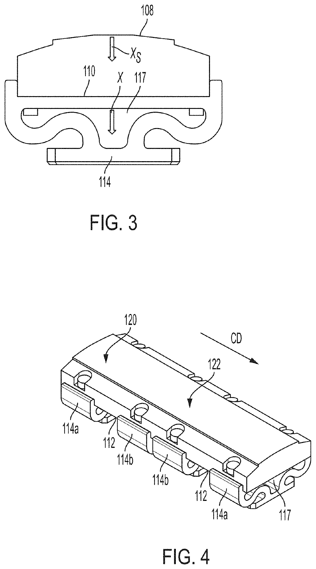
This patent is about methods and devices that use anvils with compliance. The disclosed devices have a roll with a spring element inside it, which allows for flexibility and deformation when the anvil roll is engaged with a tool. This compliance helps to compress the spring elements and improve the process of engaging a substrate with the tooling. The technical effects of this patent allow for improved quality and efficiency in the manufacturing process.

Problems solved by technology

The interaction between the two mechanisms results in deformation and wear.
For instance, in cutting operations, there may be interference between the knife and the anvil which causes deformation of the knife.
This causes localized, and often multidirectional, deformation of the knife.
This can lead to rapid degradation of the cutting surface of the knife and material fatigue of the entire knife, necessitating repair or replacement.
Moreover, shards from the knife may migrate into the web causing safety hazards.
These risks are heightened when the cutting operation involves a curvilinear knife.
In addition, there is often a very small process window for effective performance.
When the pressure applying member and the anvil are rigid, engagement for too long or too short of time, at the wrong location, where the substrates are too thick or thin, at the wrong pressure and / or at the wrong angle can lead to damage to equipment, failed or ineffective bonds, and / or tearing of the substrates.
As a result, converting processes currently require a large degree of setup in order to work within the narrow process windows.

Method used


Image

  • Compliant anvil
  • Compliant anvil
  • Compliant anvil

Examples


Embodiment Construction

Definitions

[0025]“Compliance” or “compliance value” as used herein refers to a displacement vector; a displacement vector being distance and direction that a component is deformed from its equilibrium length. The displacement vector of a spring is expressed as x in the equation F=−kx, when the spring operates according to Hooke's Law, or x in the equation F=k*f(x) when the spring does not obey Hooke's Law. Both equations are explained in more detail below. A spring may provide a compliance (displacement) to a surface or surfaces to which the spring is joined. Where more than one spring provides “a compliance” herein, said compliance is calculated using known physics and mathematical principles governing springs in parallel and series.

[0026]“Compliant,” in reference to a mechanism or a portion of a mechanism, means that the mechanism or the portion of the mechanism comprises compliance values substantially throughout the entire mechanism or entire portion, respectively, at an operati...


PUM

PropertyMeasurementUnit
Fractionaaaaaaaaaa
Lengthaaaaaaaaaa
Fractionaaaaaaaaaa

Abstract

An anvil is configured to operatively engage with a tooling agent. The anvil includes an outer surface, an opposing surface opposite the outer surface and an inner surface. One or more spring elements are disposed between the opposing surface and the inner surface. The springs provide a compliance to the anvil.

Description

FIELD OF THE INVENTION[0001]The present disclosure relates to apparatuses and methods for manufacturing articles such as absorbent articles and sanitary tissue products or components of such articles. More particularly, the present disclosure relates to apparatuses and methods involving anvil rolls such as bonding, cutting and the like.BACKGROUND OF THE INVENTION[0002]Along an assembly line, various types of articles, for example sanitary napkins, diapers, bath tissue, paper toweling, and facial tissues, may be produced by adding components to and / or otherwise modifying an advancing, continuous web of material. For example, webs or components may be bonded, embossed, cut, printed or otherwise modified while being advanced. Webs of material and component parts used to manufacture diapers may include: backsheets, topsheets, leg cuffs, waist bands, absorbent core components, front and / or back ears, fastening components, and various types of elastic webs and components such as leg elast...

Claims


Application Information

Patent Timeline
IPC IPC(8): B26F1/42B26F1/38B26F1/44B29C55/18
CPCB26F2001/402B26F1/44B26F2001/4409B29C55/18B26F1/384B26F1/42B26D7/204B41F3/14B31F2201/0728B31F2201/073B26D2007/2607B26D7/26A61F2013/15861A61F2013/15918A61F13/15723A61F13/15699A61F13/15707B29C66/431B29C66/1122B29C66/133B29C66/433B29C66/83417B29C66/83511B29C66/83513B29C66/8161B29C66/81419B29C65/02B29C65/08B29C65/48B29C65/087B29C66/4312B29C66/73921B29C66/729B29C66/7294B29C66/71B29L2031/4878B29K2023/06B29K2023/12B29K2023/0625B29K2023/0633
Inventor BUSCH, JAMES WILLIAMBURNETT, CHADSCHALLICK, JENNIFER LYNNCONGLETON, STEPHEN DOUGLAS
Owner THE PROCTER & GAMBLE COMPANY
Features
  • Generate Ideas
  • Intellectual Property
  • Life Sciences
  • Materials
  • Tech Scout
  • Unparalleled Data Quality
  • Higher Quality Content
  • 60% Fewer Hallucinations
Learn More