Fuel injection valve driving device

Active Publication Date: 2020-06-18
PANASONIC SEMICON SOLUTIONS CO LTD +1
View PDF0 Cites 2 Cited by
  • Summary
  • Abstract
  • Description
  • Claims
  • Application Information

AI Technical Summary

Benefits of technology

[0015]According to the above aspects, since the first switching element and the second switching element are closed and the fourth switching element is opened, the counter electromotive current occurring in the solenoid can be returned to the solenoid and one end side of the solenoid is clamped to a reference potential of the ground. As a result, it is possible to more accuratel

Problems solved by technology

For this reason, since the Vf of the diode changes due to environmental factors such as a counter electromotive current and a temperature, the voltage b

Method used


Image

  • Fuel injection valve driving device
  • Fuel injection valve driving device
  • Fuel injection valve driving device

Examples


Example

[0021]Hereinafter, an embodiment of a fuel injection valve driving device according to the present invention will be described with reference to the drawings.

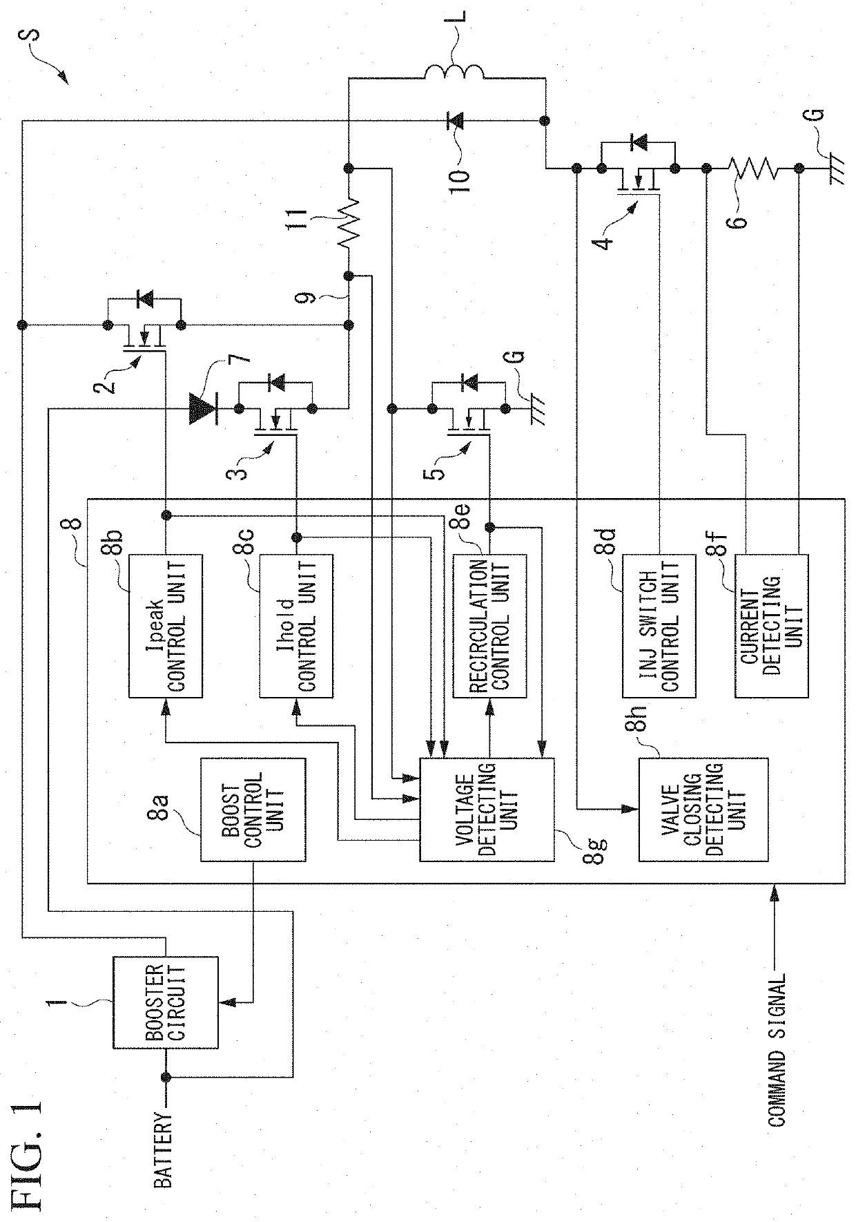
[0022]FIG. 1 is a schematic configuration diagram of a fuel injection valve driving device S of the embodiment. As shown in this drawing, the fuel injection valve driving device S of the embodiment is a driving device for driving a solenoid L of a fuel injection valve and drives the fuel injection valve by supplying power supplied from an external battery to the solenoid L on the basis of a command signal input from the outside.

[0023]As shown in FIG. 1, the fuel injection valve driving device S includes a booster circuit 1, a first semiconductor switch 2 (a first switching element), a second semiconductor switch 3 (a second switching element), a third semiconductor switch 4 (a third switching element), a fourth semiconductor switch 5 (a fourth switching element), a current detecting resistor 6, a backflow preventing diode 7, a ...


PUM


Abstract

This fuel includes: a first switching element disposed between a booster circuit boosting a battery power and one end of a solenoid; a second switching element disposed between a battery and one end of the solenoid; a third switching element disposed between the other end of the solenoid and a ground; a fourth switching element disposed between one end of the solenoid and a ground; and a control unit configured to control open/closed states of the first switching element, the second switching element, the third switching element, and the fourth switching element. The control unit is configured to open the fourth switching element during a valve closing detection period of detecting closing of a fuel injection valve and to detect the closing of the fuel injection valve on the basis of a change in voltage of the other end of the solenoid.

Description

CROSS REFERENCE TO RELATED APPLICATION[0001]The present invention claims priority under 35 U.S.C. § 119 to Japanese Patent Application No. 2018-234459, filed on Dec. 14, 2018, the entire content of which is incorporated herein by reference.BACKGROUND OF THE INVENTIONField of the Invention[0002]The present invention relates to a fuel injection valve driving device.Description of Related Art[0003]For example, Japanese Patent Publication No. 6383760 discloses a control device of an internal combustion engine provided with a fuel injection valve with a solenoid. The control device disclosed in Japanese Patent Publication No. 6383760 is used to control the internal combustion engine by driving the solenoid of the fuel injection valve and includes a plurality of switching elements for switching a power supplying state from a booster circuit or a battery to the solenoid.SUMMARY OF THE INVENTION[0004]In Japanese Patent Publication No. 6383760, the timing when the valve body comes into conta...

Claims


Application Information

Patent Timeline
IPC IPC(8): F02M51/00F02D41/30B05B1/30
CPCF02D41/30B05B1/3053F02M51/005F02D41/20F02D41/22F02D2041/2003F02D2041/2068F02D2041/224F02D2041/2055F02D2041/2075F02D2041/2041F02D2041/2058
Inventor OGAWA, ATSUSHIKATO, MOTOAKINOMURA, KENGOKURODA, KEISUKERYU, TAKASHI
Owner PANASONIC SEMICON SOLUTIONS CO LTD
Why Eureka
Try Eureka