Hydraulic tensioning device for a traction mechanism drive

A technology for tensioning devices and tools, which is applied in the direction of transmission devices, valve devices, engine components, etc., and can solve problems such as installation difficulties

Inactive Publication Date: 2009-01-07
SCHAEFFLER TECH AG & CO KG
View PDF10 Cites 0 Cited by
  • Summary
  • Abstract
  • Description
  • Claims
  • Application Information

AI Technical Summary

Problems solved by technology

It is therefore very difficult to install such a chain tensioner with an automatic assembly machine without interference

Method used


Image

  • Hydraulic tensioning device for a traction mechanism drive
  • Hydraulic tensioning device for a traction mechanism drive

Examples


Embodiment Construction

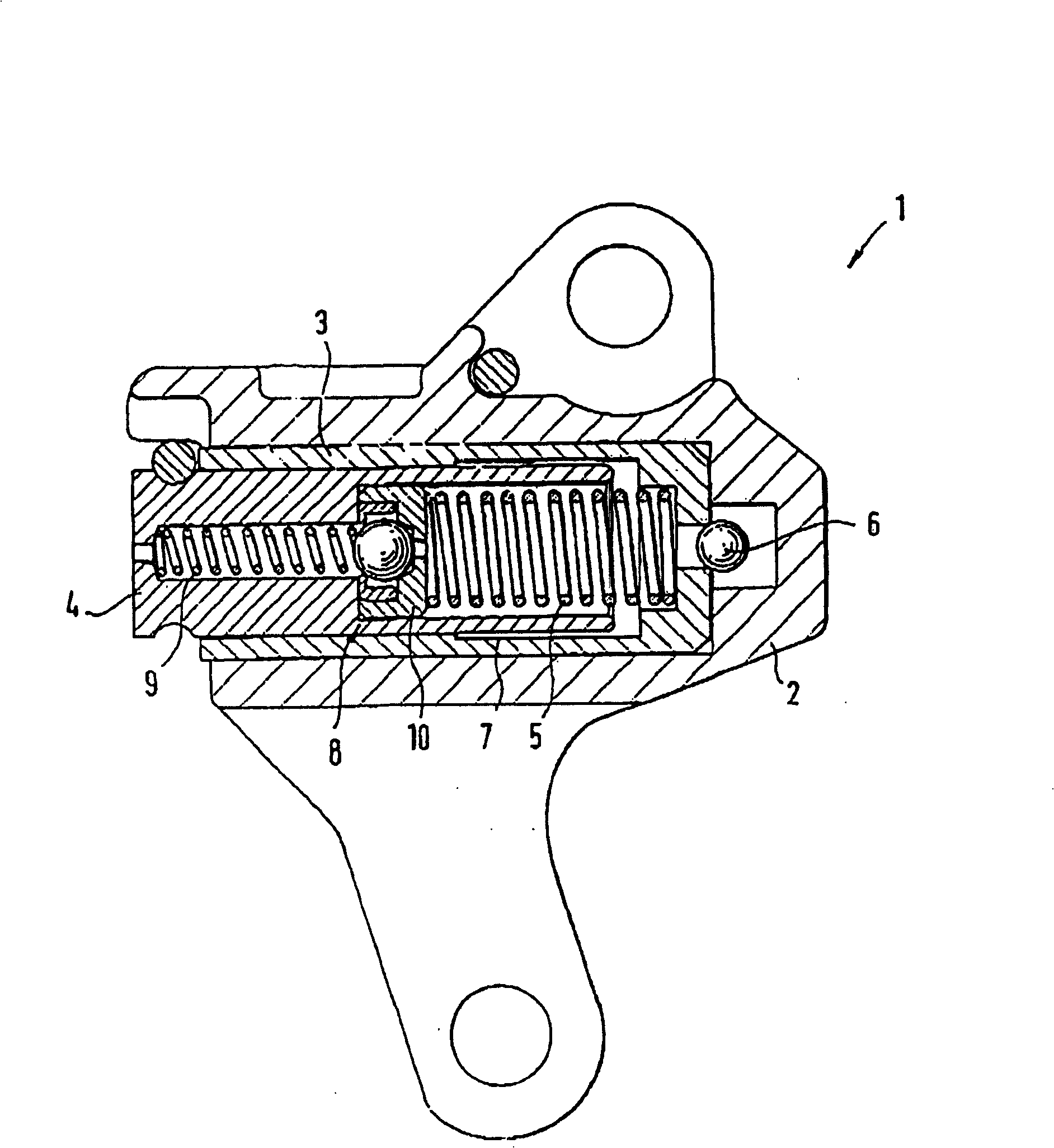
[0020] figure 1 An assembly drawing showing a partial section of the tensioner. The tensioning device shown is a chain tensioner for tensioning the drive chain of an internal combustion engine.

[0021] The hydraulic tensioning device 1 basically consists of a housing 2 into which a housing 3 of the tensioner hydraulics is inserted. A tensioner piston 4 is axially movably accommodated inside the tensioner hydraulic part housing 3 . During work, the front side of the tensioner piston 4 is closely attached to the transmission chain.

[0022] The tensioner hydraulic housing 3 and the tensioner piston 4 , which are simultaneously used as cylinders for the tensioner piston 4 , form a pressure chamber, which is filled with a hydraulic fluid, usually engine oil. A tensioner main spring 5 is arranged in the pressure chamber, which is designed as a pressure spring and presses the tensioner piston 4 outwards against the chain until a balance between the spring force and the pressing ...


PUM


Abstract

A hydraulic tensioning device is provided for a traction mechanism drive, in particular for a chain or belt drive of an internal combustion engine. The device includes a tensioning piston which is guided in a displaceable manner in a cylinder, with a pressure chamber being defined between the tensioning piston and the cylinder which is used to receive hydraulic fluid. A pressure relief valve is provided which limits the pressure in the pressure chamber. The pressure relief valve (8) includes, at least partially, a pre-assembled assembly (10) which can be inserted or is inserted into the tensioning piston (4).

Description

technical field [0001] The invention relates to a hydraulic tensioning device for traction means drives, in particular for internal combustion engine chain or belt drives, with a tensioning piston guided in movement in a cylinder, a hydraulic fluid for accommodating hydraulic fluid through the tensioning piston and cylinder Defined pressure chamber and an overpressure valve limiting the pressure in the pressure chamber. Background technique [0002] DE 40 35 823 C1 describes a hydraulic tensioning device for traction means drives such as chain or belt drives on internal combustion engines. The longitudinal movement of the tensioning piston, which presses against the chain, is accommodated in a cylinder. The tensioning piston and cylinder delimit a pressure chamber for containing hydraulic fluid. The tensioning movement of the tensioning piston in the direction of the chain enlarges the pressure chamber, wherein the non-return valve can be opened and engine oil can flow int...

Claims


Application Information

Patent Timeline
Patent Type & Authority Patents(China)
IPC IPC(8): F16H7/08F16K17/04
CPCF16K17/0406F16H2007/0859F16H2007/0814F16H2007/0812F16H2007/0806F16H7/0848
Inventor 莱因哈德·科赫
Owner SCHAEFFLER TECH AG & CO KG
Why Eureka
Try Eureka