Display device for injection molding machine

Active Publication Date: 2020-07-02
FANUC LTD
View PDF20 Cites 0 Cited by
  • Summary
  • Abstract
  • Description
  • Claims
  • Application Information

AI Technical Summary

Benefits of technology

[0017]The present invention enables to provide a display device for an injection molding machine cap

Problems solved by technology

It takes a long time to find and select the next scre

Method used


Image

  • Display device for injection molding machine
  • Display device for injection molding machine
  • Display device for injection molding machine

Examples


Example

First Embodiment

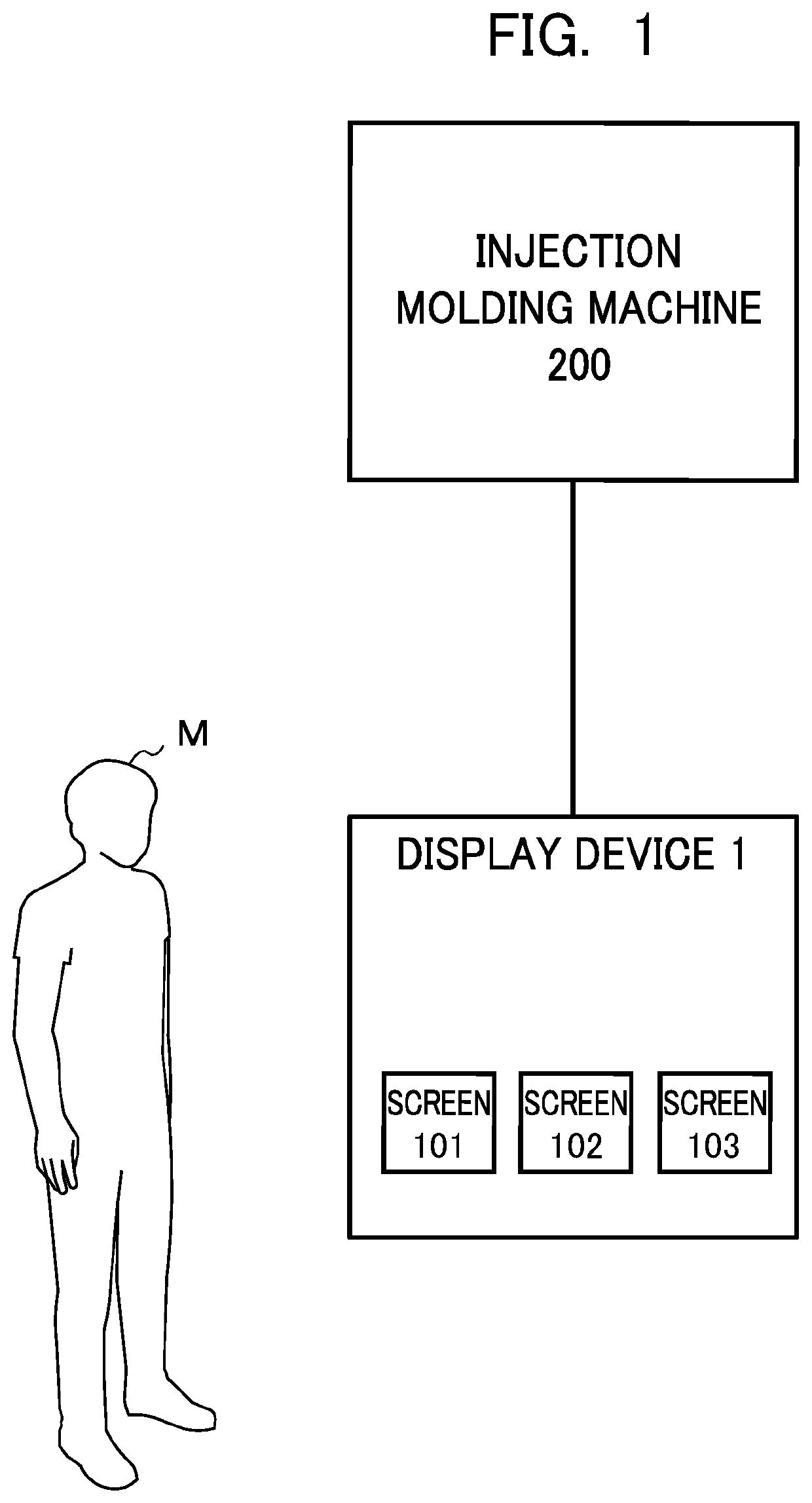
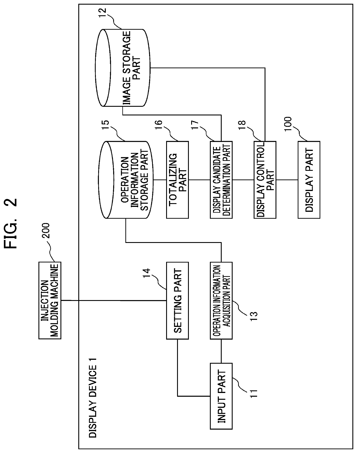
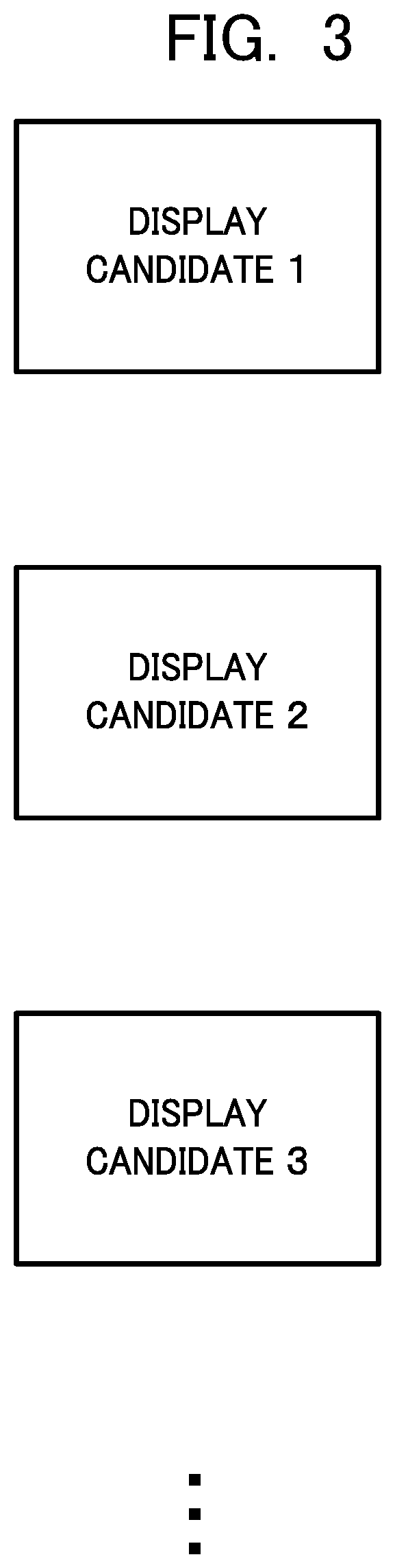
[0029]The display device 1 for the injection molding machine 200 according to the first embodiment of the present invention is described below by referring to FIG. 1 to FIG. 4. As shown in FIG. 1, the display device 1 for the injection molding machine 200 according to the present embodiment is arranged to be connected to the injection molding machine 200. The display device 1 for the injection molding machine 200 includes a display part 100 capable of displaying a predetermined screen image and capable of displaying a candidate for a next screen image to transition to as a display candidate. As shown in FIG. 2, the display device 1 for the injection molding machine 200 includes an input part 11, an image storage part 12, an operation information acquisition part 13, a setting part 14, an operation information storage part 15, a totalizing part 16, a display candidate determination part 17, and a display control part 18.

[0030]The display part 100 is an image output de...

Example

Second Embodiment

[0053]The display device 1 for the injection molding machine 200 according to the second embodiment of the present invention is described below. In the description of the second embodiment, the same components as those of the above-described embodiment are denoted by the same reference numerals, and descriptions thereof are omitted or simplified. The display device 1 for the injection molding machine 200 according to the second embodiment is different from that according to the first embodiment, in that the totalizing part 16 totalizes the operations related to the predetermined screen image being displayed on the basis of the predetermined screen image and the number of times of a combination of the next screen image transitioned to and the original predetermined screen image as operation information.

[0054]In an example, the totalizing part 16 totalizes the number of times of transition to the next screen image transitioned to for each predetermined screen image. T...

Example

Third Embodiment

[0057]The display device 1 for the injection molding machine 200 according to the third embodiment of the present invention is described below by referring to FIG. 5. In the description of the third embodiment, the same components as those of the above-described embodiments are denoted by the same reference numerals, and descriptions thereof are omitted or simplified. As shown in FIG. 5, the display device 1 for the injection molding machine 200 according to the third embodiment is different from those according to the first and second embodiments, in that the display device 1 further includes an operation state acquisition part 19. Further, the display device 1 for the injection molding machine 200 according to the third embodiment is different from those according to the first and second embodiments, in that the display candidate determination part 17 determines candidates for the screen images to be display candidates on the basis of the acquired operating state.

[...


PUM


Abstract

The present invention is to provide a display device for an injection molding machine capable of displaying a screen image to be a display candidate without imposing a burden on an operator.
A display device for an injection molding machine includes a display part capable of displaying a predetermined screen image and capable of displaying a candidate for a next screen image to transition to as a display candidate. The display device for the injection molding machine includes an operation information acquisition part configured to acquire, as operation information, operations performed related to a predetermined screen image being displayed, a totalizing part configured to totalize the operations related to the predetermined screen image being displayed on the basis of the acquired operation information, a display candidate determination part configured to determine the candidate for the screen image to be the display candidate on the basis of a totalized result, and a display control part configured to display not only the predetermined screen image but also the determined display candidate on the display part.

Description

[0001]This application is based on and claims the benefit of priority from Japanese Patent Application No. 2018-245328, filed on 27 Dec. 2018, the content of which is incorporated herein by reference.BACKGROUND OF THE INVENTIONField of the Invention[0002]The present invention relates to a display device for an injection molding machine.Related Art[0003]Conventionally, an injection molding machine is a machine tool configured to inject and mold, for example, resin. Before the injection molding machine operates, a value related to the operation of the injection molding machine is set in advance to the injection molding machine. The injection molding machine operates on the basis of the set value.[0004]There are many types of screen images to be displayed on the display device for the injection molding machine. For example, there are fifty types of screen images to be displayed on the display device for the injection molding machine. It takes a long time to find and select the next scr...

Claims


Application Information

Patent Timeline
IPC IPC(8): G06F3/0484G06F3/0482B29C45/17
CPCB29C45/1774G06F3/0482G06F3/0484B29C45/76G06F3/04842G06N20/00B29C2045/7606
Inventor ZHUO, XINMINMARUYAMA, JUNPEI
Owner FANUC LTD
Why Eureka
Try Eureka