Optical Axis Deviation Detecting Device, Target Detection Device, and Movable Body

Pending Publication Date: 2021-08-26
MITSUBISHI ELECTRIC CORP
View PDF0 Cites 0 Cited by
  • Summary
  • Abstract
  • Description
  • Claims
  • Application Information

AI Technical Summary

Benefits of technology

[0011]According to the present invention, an optical axis deviation detecting device capabl

Problems solved by technology

Unfortunately, in the technique described in PTL 1, the user has to move a movable body to the place whe

Method used


Image

  • Optical Axis Deviation Detecting Device, Target Detection Device, and Movable Body
  • Optical Axis Deviation Detecting Device, Target Detection Device, and Movable Body
  • Optical Axis Deviation Detecting Device, Target Detection Device, and Movable Body

Examples


Example

First Embodiment

APPLICATION EXAMPLES

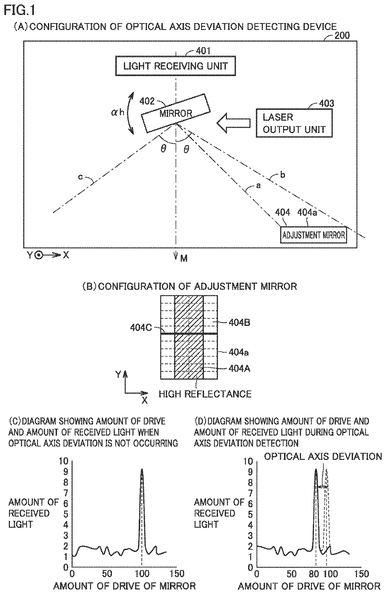
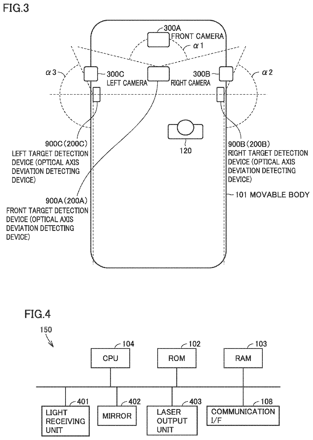
[0033]In self-driving of a movable body, remote sensing (remote measurement) technique for detecting the presence / absence of a target and the distance from the movable body to the target is employed in a target detection device 900. Target detection device 900 is typically a LIDAR (Light Detection and Ranging, Laser Imaging Detection and Ranging).

[0034]The resolutions in a scan range in the horizontal direction and a scan range in the vertical direction are defined by angles for each individual target detection device 900. Target detection device 900 can perform three-dimensional measurement in a wide range by detecting a target in a certain range. In target detection device 900, when an optical axis deviation of laser light occurs, an error in distance from the target to the movable body increases. It is therefore important to detect the occurring optical axis deviation. The optical axis deviation detecting device in the present embodiment detect...

Example

Second Embodiment

[0201]The foregoing first embodiment is based on the premise that when the vertical direction is fixed and mirror 402 is driven in the horizontal direction, mirror 402 is driven along the horizontal direction appropriately although an optical axis deviation in the horizontal direction may occur. Furthermore, the foregoing first embodiment is based on the premise that when the horizontal direction is fixed and mirror 402 is driven in the vertical direction, mirror 402 is driven along the vertical direction appropriately although an optical axis deviation in the vertical direction may occur. Hereinafter, such a premise is referred to as “linearity is ensured”.

[0202]In the present embodiment, an embodiment in which linearity is not ensured will be described. That is, in the present embodiment, when the vertical direction is fixed and mirror 402 is driven in the horizontal direction, it may be driven with a skew from the horizontal direction (in a direction deviating fr...

Example

Third Embodiment

[0222]A third embodiment will now be described. In the second embodiment, as illustrated in FIG. 16(D), in a case where a third optical axis deviation is not occurring, the amount of drive at the peak is the amount of non-deviation drive (in the example in FIG. 16, the amount of drive corresponding to four cells). However, even in a case where a third optical axis deviation is occurring, the amount of drive at the peak is the amount of non-deviation drive in some cases.

[0223]FIG. 18(A) is a diagram showing a case where the amount of drive at the peak is the amount of non-deviation drive (the amount of drive equivalent to four cells) when a third optical axis deviation is occurring. As shown in FIG. 18(A), even in a case where a third optical axis deviation is occurring, the amount of drive at the peak is the amount of non-deviation drive (the amount of drive equivalent to four cells). Rather than the third optical axis deviation shown in FIG. 18(A), a third optical a...


PUM


Abstract

An optical axis deviation detecting device includes a mirror to perform driving to change an output direction of output light, an adjustment mirror to reflect light output from the mirror and including a low reflection region and a high reflection region, a light receiver to receive light from the adjustment mirror, a non-deviation peak memory to store the amount of drive at which the amount of received light reaches a peak or an inverse peak based on reflection by the adjustment mirror when optical axis deviation is not occurring, a peak acquisition circuit to acquire the amount of drive at the time of a peak or an inverse peak of the amount of received light by driving of the mirror during an optical axis deviation detection mode, and a first deviation amount detector to detect an optical axis deviation based on the stored and acquired amounts of drive.

Description

TECHNICAL FIELD[0001]The present invention relates to an optical axis deviation detecting device for detecting an optical axis deviation, a target detection device, and a movable body.BACKGROUND ART[0002]Conventionally, a measurement device, mountable on a movable body (for example, a vehicle) capable of autonomous driving, to measure the distance between the movable body and a target is known. The measurement device emits laser light in a predetermined direction (for example, forward), receives reflected laser light returning from the target, and detects the distance to the target based on the reflected laser light. Such a measurement device need to accurately specify the optical axis direction of laser light.[0003]Methods of detecting the amount of deviation from a reference direction of the optical axis have been proposed. For example, PTL 1 proposes a method of detecting the amount of deviation using a target board including two regions with different reflectances for output las...

Claims


Application Information

Patent Timeline
IPC IPC(8): G01B11/27G01S7/497G01S17/08
CPCG01B11/272G01S17/08G01S7/497G01C3/00G01C3/06G01S7/4972G01S17/931G01S17/42
Inventor KAWASAKI, SUMITOSHI
Owner MITSUBISHI ELECTRIC CORP
Why Eureka
Try Eureka