Buffer storage system for overhead conveyor systems

Inactive Publication Date: 2020-07-09
FERAG AG
View PDF0 Cites 2 Cited by
  • Summary
  • Abstract
  • Description
  • Claims
  • Application Information

AI Technical Summary

Benefits of technology

[0082]Such an advantageous transport unit advantageously has two or more carrier channels situated adjacently and in parallel on a horizontal plane. This allows the transport capacity of the transport unit to be maximized.
[0083]In one advantageous variant of such a transport unit, the projections that form the un

Problems solved by technology

Manual filling of provided unoccupied transport units such as transport bags, or manual removal of goods from the transport bags allows flexible handling of various goods, but is slow and costly.
However, use in continuous flows of goods via batchwise processing is inefficient.
Thus, a sorting action cannot be efficiently achieved.
On the other hand, the sorting function is optimized for efficient sorting and conveying of groups of transport goods, but not for the efficient control of flows of goods, in which

Method used


Image

  • Buffer storage system for overhead conveyor systems
  • Buffer storage system for overhead conveyor systems
  • Buffer storage system for overhead conveyor systems

Examples


Embodiment Construction

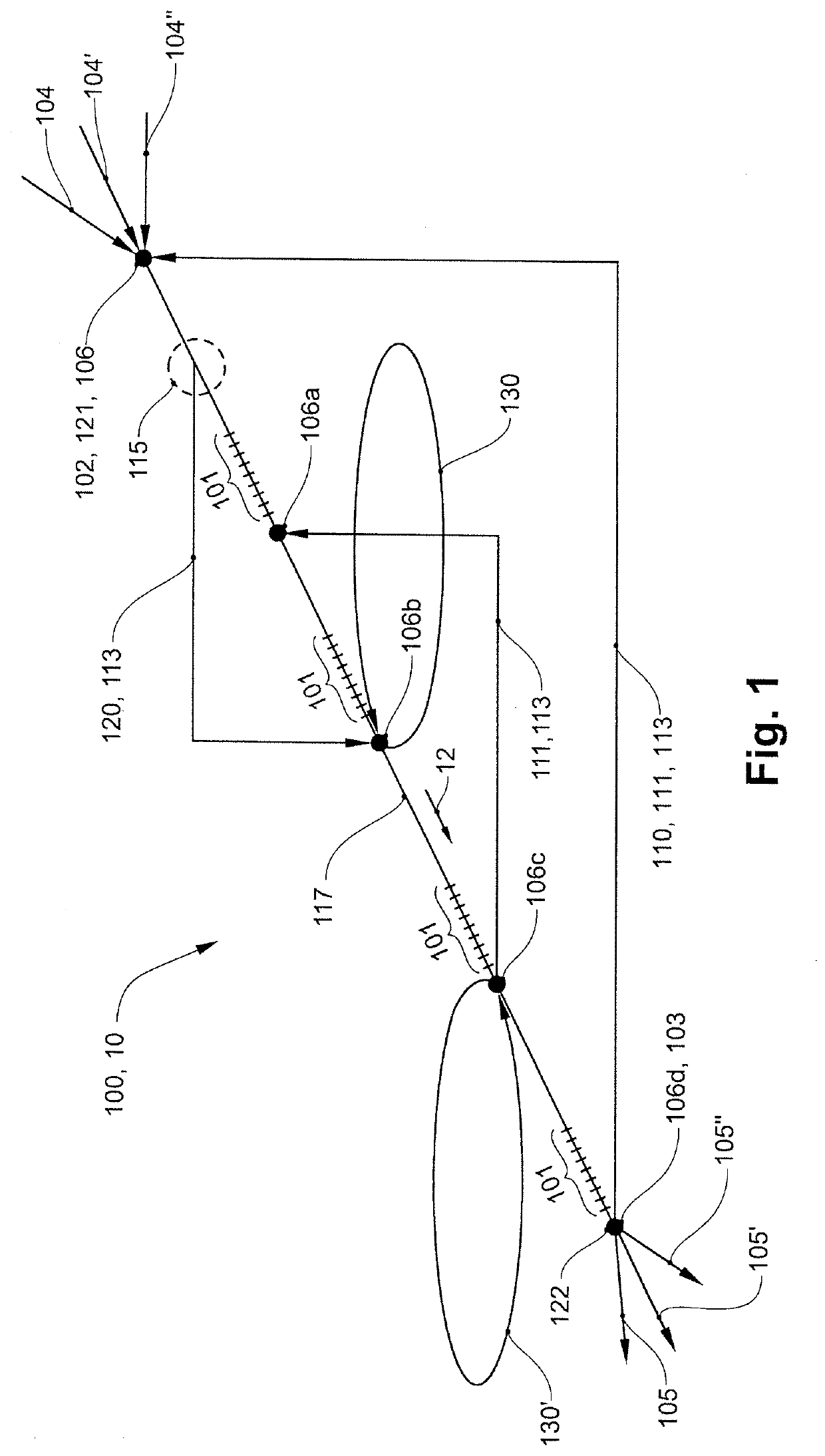
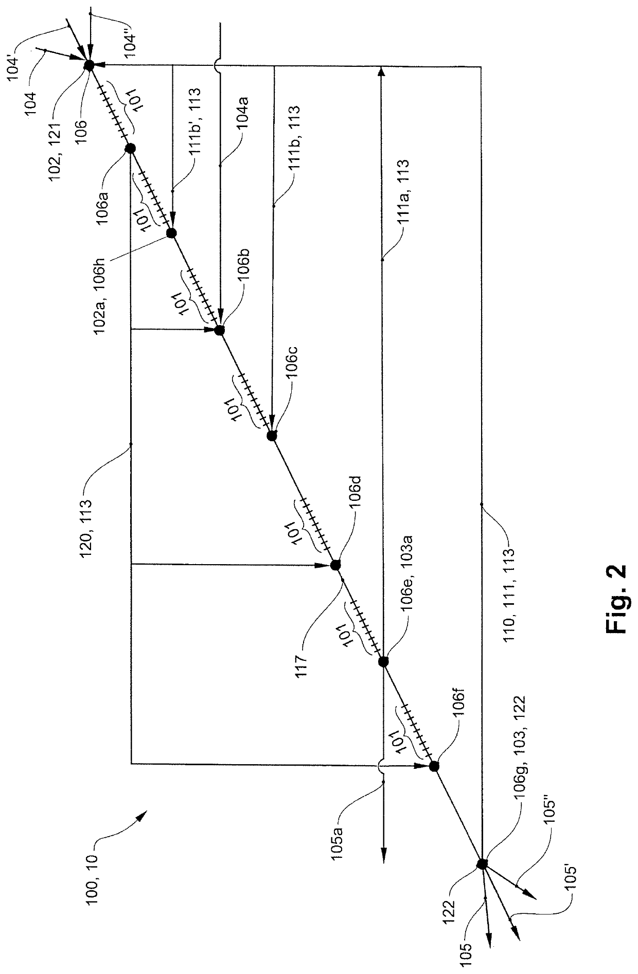
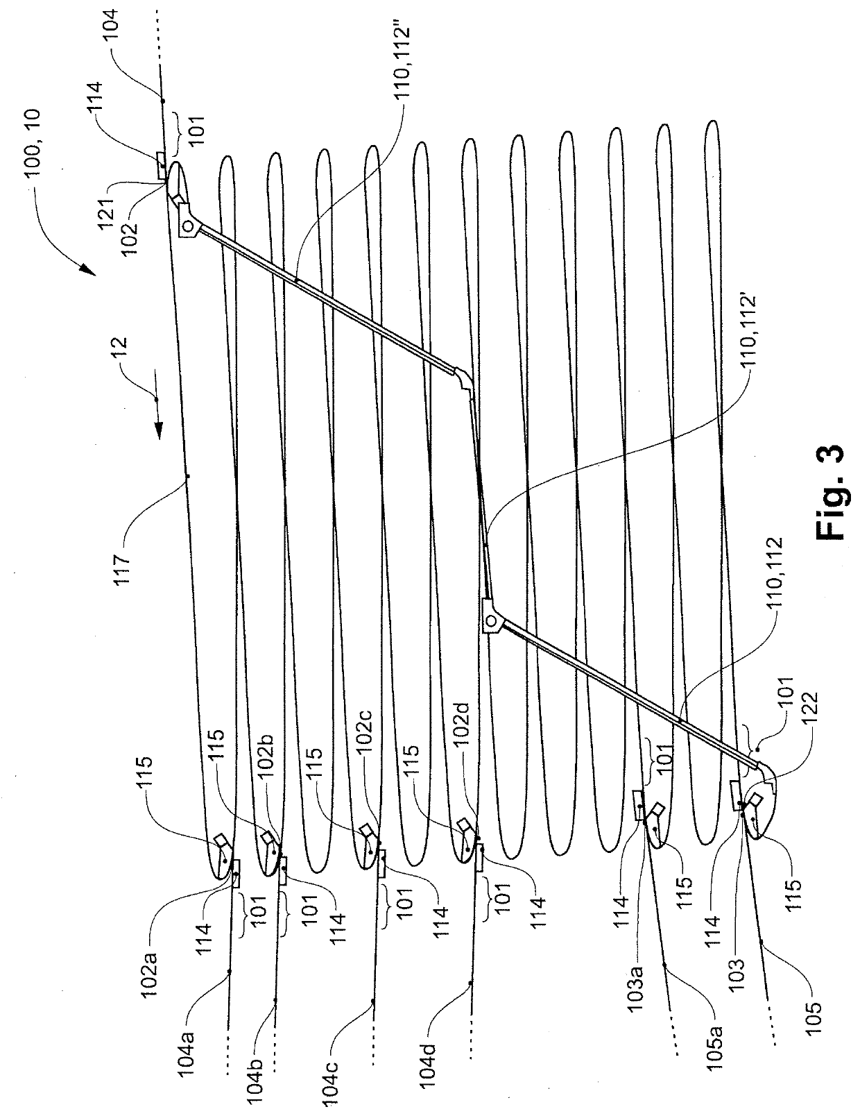
[0100]One possible embodiment variant of a buffer storage device 100 according to the invention for an overhead conveyor system 10 having individually conveyable transport units is illustrated strictly schematically in FIG. 1. A buffer section 117 extends downwardly from a starting point 121 of the buffer section to an end point 122 of the buffer section. Transport units can move downstream, driven by gravity, on the downwardly sloping buffer section along the conveying direction 12.

[0101]A bypass section 113 in the form of a return section 110 leads from the end point 122 of the buffer section 117 back to the starting point 102 of the buffer section 117, and together with the buffer section 117 forms a closed conveying path.

[0102]In the exemplary embodiment shown, multiple feed sections 104, 104′, 104″ come together at a feed point 102, which in this case is identical to the starting point 121 of the buffer section; transport units may be supplied to the feed sections from various ...


PUM


Abstract

A buffer storage device (100) for an overhead conveyor system (10) having individually conveyable transport units (40), with a closed conveying path that includes a buffer section (117) along which transport units are conveyable downstream, a feed section (104) for feeding transport units to a feed point (102) of the buffer section, a discharge section (105) for discharging transport units from a discharge point (103) of the buffer section, and one or more additional bypass sections (113) which in each case connect a starting point along the buffer section to a destination point along the buffer section.

Description

CROSS-REFERENCE TO RELATED APPLICATIONS[0001]Swiss Patent Application 00019 / 19, filed 9 Jan. 2019, the priority document corresponding to this invention, to which a foreign priority benefit is claimed under Title 35, United States Code, Section 119, and Title 37, United States Code, Section 1.55, and its entire teachings are incorporated, by reference, into this specification.BACKGROUND OF THE INVENTIONField of the Invention[0002]The present invention pertains to the field of transport and conveying technology. The invention relates to buffer storage devices for overhead conveyor systems having individually conveyable transport units, and overhead conveyor systems having such buffer storage devices.Discussion of Related Art[0003]In logistics, in particular intralogistics, the general pressure on costs in the distribution and supply of goods is addressed, among other things, by increasing the efficiency of automated systems.[0004]The goods stored and kept in large warehouses, in part...

Claims


Application Information

Patent Timeline
IPC IPC(8): B65G1/04B65G1/08B65G9/00
CPCB65G1/08B65G1/0457B65G9/006B65G1/0485B65G17/20B65G47/61B65G47/69B65G1/04B65G17/485
Inventor SIGRIST, SERGIO
Owner FERAG AG
Why Eureka
Try Eureka