Unlock instant, AI-driven research and patent intelligence for your innovation.

Compensation of environmentally-induced drift in an electrochemical carbon-monoxide sensor

a technology of carbon monoxide sensor and environmental compensation, which is applied in the field of compensating environmental-induced drift in electrochemical carbon monoxide sensor, can solve the problems of reducing the ability of the associated system to respond correctly, inaccurate and/or unstable measurements, and easy drift of electronic sensors

Active Publication Date: 2020-08-13
GOOGLE LLC
View PDF0 Cites 3 Cited by
  • Summary
  • Abstract
  • Description
  • Claims
  • Application Information

AI Technical Summary

Benefits of technology

The invention is a hazard detection device that can detect the presence of carbon monoxide (CO) using a humidity sensor, temperature sensor, and CO sensor. The device can correct the CO measurement based on the ambient temperature and humidity to get a more accurate measurement. The device can also detect a drift in the CO measurement and generate an alarm based on the corrected measurement. The instability of the CO sensor can be caused by changes in the ambient temperature or humidity, and the device can compensate for these changes to provide accurate readings. The technical effects of this invention are to improve the accuracy and reliability of hazard detection and minimize the likelihood of false alarms caused by sensor drift.

Problems solved by technology

Electronic sensors are known to be susceptible to drift, which occurs when the sensor output varies independently of or disproportionately to the physical property being measured.
This variation results in inaccurate and / or unstable measurements, thereby reducing the ability of the associated system to correctly respond.
In the context of smoke and carbon monoxide (CO) detection devices, sensor drift can cause the device to fail to alert or to alert needlessly.
Ambient environmental factors such as vibration, contamination, temperature, and humidity may exacerbate a sensor's tendency to drift.
For example, a manufacturer may physically isolate the sensing element from the ambient environment, at the expense of reduced sensitivity and slowed response.
Alternatively, a manufacturer may attempt to regulate localized environmental conditions, such as temperature, to stabilize the degree of drift in exchange for increased device cost and complexity.

Method used


Image

  • Compensation of environmentally-induced drift in an electrochemical carbon-monoxide sensor
  • Compensation of environmentally-induced drift in an electrochemical carbon-monoxide sensor
  • Compensation of environmentally-induced drift in an electrochemical carbon-monoxide sensor

Examples


Embodiment Construction

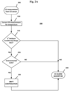
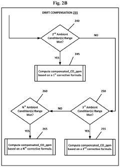
[0013]As previously disclosed, environmental sensors often exhibit various levels of drift. Sensor manufacturers may provide technical information that describes the extent of drift that can be expected, the conditions under which drift will occur, or the like. However, such information may be inaccurate or may change over time or with different sensors. Therefore, it is desirable to compensate for sensor drift in a hazard detection device, thereby ensuring that the system will provide an alert at the correct time under the circumstances.

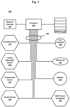
[0014]The present subject matter discloses a hazard detection device and method for compensating for the effects of elevated environmental conditions on measured values from an electrochemical sensor. The disclosed hazard detection device and associated method may be applicable to drift compensation for a broad range of sensors, although the example embodiments disclosed herein refer to a carbon monoxide (CO) detection device utilizing at least a CO...


PUM

PropertyMeasurementUnit
temperatureaaaaaaaaaa
relative humidityaaaaaaaaaa

Abstract

Methods of the disclosed subject matter provide compensation for sensor drift in a hazard detection device having a plurality of sensors coupled to a processor to determine that a carbon monoxide sensor is drifting and to compensate for the drift by calculating a corrected carbon monoxide measurement value based on the ambient environmental conditions.

Description

BACKGROUND[0001]Electronic sensors are known to be susceptible to drift, which occurs when the sensor output varies independently of or disproportionately to the physical property being measured. This variation results in inaccurate and / or unstable measurements, thereby reducing the ability of the associated system to correctly respond. In the context of smoke and carbon monoxide (CO) detection devices, sensor drift can cause the device to fail to alert or to alert needlessly.[0002]Ambient environmental factors such as vibration, contamination, temperature, and humidity may exacerbate a sensor's tendency to drift. To mitigate drift and the resulting loss of sensor accuracy, manufacturers employ various techniques. For example, a manufacturer may physically isolate the sensing element from the ambient environment, at the expense of reduced sensitivity and slowed response. Alternatively, a manufacturer may attempt to regulate localized environmental conditions, such as temperature, to...

Claims


Application Information

Patent Timeline
Patent Type & Authority Applications(United States)
IPC IPC(8): G01N33/00
CPCG01N33/0006G01N33/0034G01N33/004Y02A50/20
Inventor GHADIALI, ADITYABAJAJ, KUNAL KISHORE
Owner GOOGLE LLC