Supercharge Your Innovation With Domain-Expert AI Agents!

Hybrid drawer handle and release mechanism

a technology of release mechanism and handle, which is applied in the field of handle mechanism, can solve the problems of spiking of the contents of the drawer, difficult to adapt for use in the vehicle, and relatively complicated known release mechanism

Active Publication Date: 2020-08-20
ALLEGIS CORP
View PDF0 Cites 0 Cited by
  • Summary
  • Abstract
  • Description
  • Claims
  • Application Information

AI Technical Summary

Benefits of technology

The mechanism provides a cost-effective, reliable, and secure way to open drawers without accidental release, even during vehicle movement, ensuring contents remain intact.

Problems solved by technology

The known release mechanisms have been relatively complicated and costly to manufacture, maintain and service.
In addition, the known handles, drawer slides and cabinets, have been difficult to adapt for use in a vehicle due to the inadvertent release of the latching mechanism of the drawers during movement of the vehicle.
Unintentional release of the drawer latch results in the sliding of the drawer outwardly from the cabinet, and the spewing of the contents of the drawer within the interior of the vehicle.

Method used


Image

  • Hybrid drawer handle and release mechanism
  • Hybrid drawer handle and release mechanism
  • Hybrid drawer handle and release mechanism

Examples


Embodiment Construction

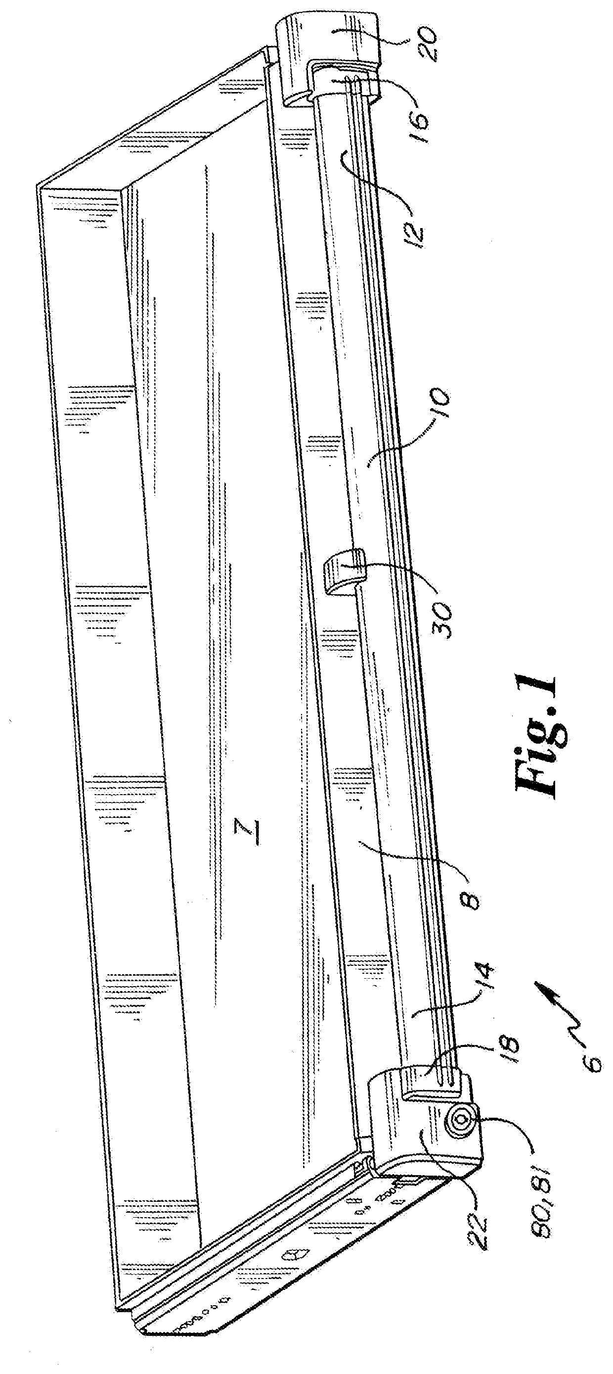
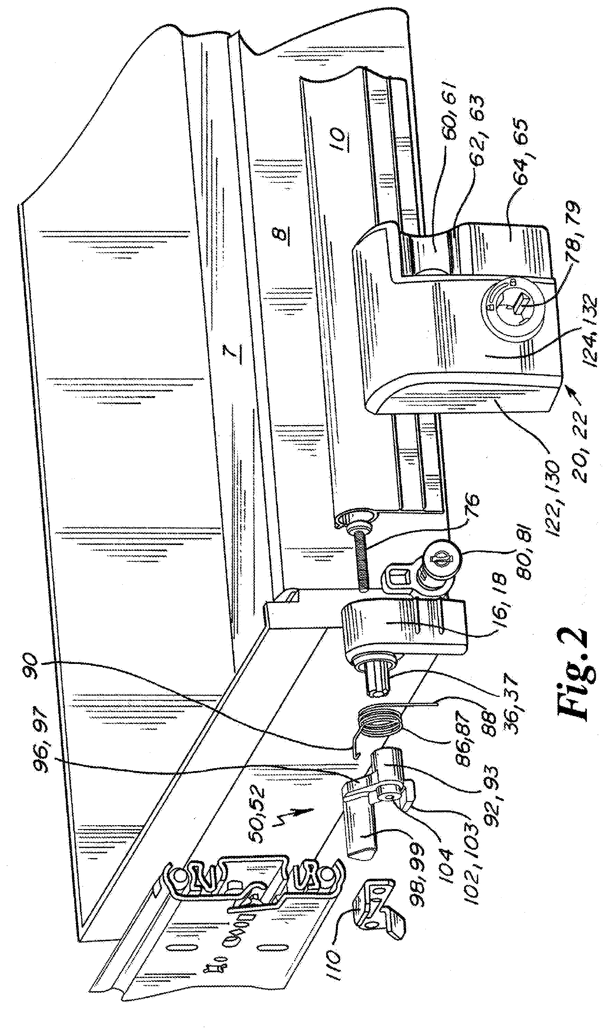
[0070]In general the hybrid drawer handle and release mechanism is referred to by numeral 6. The hybrid drawer handle and release mechanism 6 is generally engaged to a drawer 7 having a front wall 8.

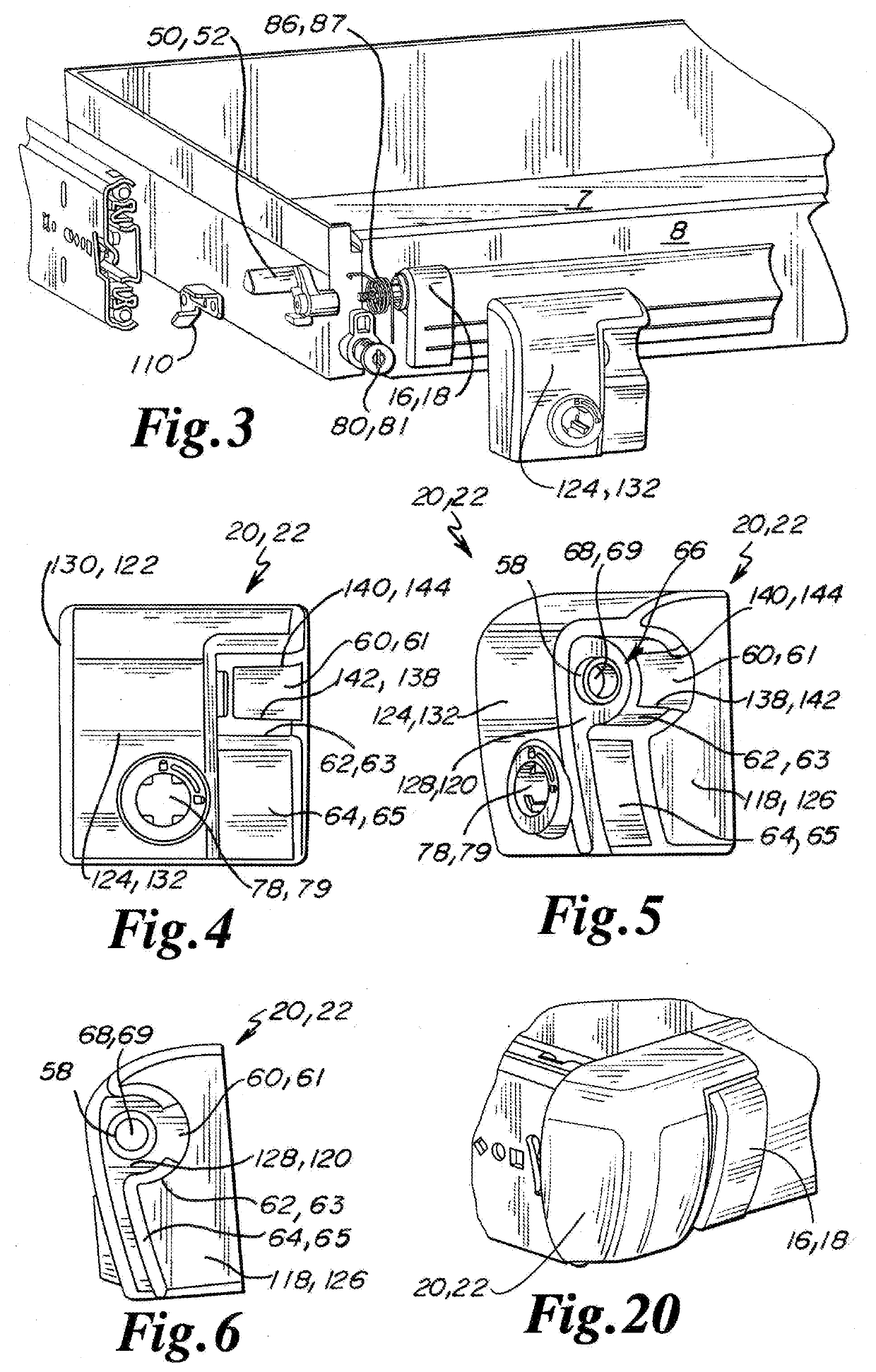
[0071]The hybrid drawer handle and release mechanism 6 preferably includes a handle 10 having a first handle end 12 and a second handle end 14. Each of the respective first and second handle ends 12, 14 are inserted into a first end cap interface 16 and a second end cap interface 18. In at least one embodiment, the first end cap interface 16 is rotatably engaged to a first end cap 20 and the second end cap interface 18 is rotatably engaged to a second end cap 22.

[0072]In a preferred embodiment, an interior or central portion of the handle 10 is disposed within and is pivotal relative to a central support 30. The central support 30 is preferably centrally affixed to the front wall 8 approximately equal distances between the first handle end 12 and the second handle end 14.

[0073]In at leas...


PUM


Abstract

A drawer release mechanism has a handle having ends, a cylindrical portion and a flange. A pair of end cap interfaces are engaged to the ends of the handle. The end cap interfaces have rotational shafts, cylindrical receiving portions, receiving slots, and flange slots. A pair of end caps are exterior to the end cap interfaces, the end caps have flange recesses, rotation surfaces, shaft openings, and cam receiving areas, where the rotational shafts are disposed through the shaft openings, the receiving portions are adjacent to the rotation surfaces, and the flange slots are disposed in the flange recesses. The end caps are attached to a drawer. A cam is engaged to each of the rotational shafts. Each cam includes a shaft receiver, an actuator support and a cam actuator. The cams engage levers to release a drawer from a cabinet upon actuation of the handle.

Description

CROSS-REFERENCE TO RELATED APPLICATIONS[0001]This application is a continuation of U.S. Utility patent application Ser. No. 16 / 414,345 filed May 16, 2019 and issued as U.S. patent Ser. No. 10 / 641,010 on May 5, 2020, which claims the benefit of U.S. Provisional Patent Application Ser. No. 62 / 674,261 filed May 21, 2018, which is incorporated by reference herein in its entirety and which claims the benefit of U.S. Provisional Patent Application Ser. No. 62 / 699,215 filed Jul. 17, 2018, which is incorporated by reference herein in its entirety.FIELD OF THE INVENTION[0002]The invention is directed to a handle mechanism as attached to a sliding drawer, where the handle may be lifted / rotated to actuate a latch integral to a cabinet, the handle mechanism being used to release the drawer slide from a secured position relative to the cabinet.BACKGROUND[0003]Extruded handles which are pivotally engaged to a drawer, drawer slide and cabinet, which have been used to provide access into a drawer, ...

Claims


Application Information

Patent Timeline
Patent Type & Authority Applications(United States)
IPC IPC(8): E05B65/46A47B88/944A47B88/423A47B88/919
CPCA47B88/944A47B88/423A47B88/919A47B2088/939E05B65/46E05B13/002E05B7/00A47B2095/025A47B2095/022
Inventor SONNEY, TYE S.
Owner ALLEGIS CORP
Features
  • R&D
  • Intellectual Property
  • Life Sciences
  • Materials
  • Tech Scout
  • Unparalleled Data Quality
  • Higher Quality Content
  • 60% Fewer Hallucinations
Learn More