
Display method and display system

Inactive Publication Date: 2020-08-27
SEIKO EPSON CORP
View PDF0 Cites 4 Cited by
  • Summary
  • Abstract
  • Description
  • Claims
  • Application Information

AI Technical Summary

Benefits of technology

The present patent is about a display method and system that allows a terminal apparatus to acquire marker information and generate association information that links the marker information with a display target image. The detection apparatus can then detect the marker on a display surface and extract its characteristic, identifying the associated image based on the marker information and the association information. The display apparatus can then determine the position where the image is displayed and display it accordingly. This allows for the display to dynamically update the image based on the marker's movement. The technical effect of this patent is to provide a more efficient and effective way of displaying images that are associated with markers, making the process easier and more user-friendly.

Problems solved by technology

In a case where the number of images displayed on the display surface increases, however, it is difficult in some cases to prepare markers the number of which is equal to the number of images.

Method used


Image

  • Display method and display system
  • Display method and display system
  • Display method and display system

Examples


first embodiment

1. Overview of Display System

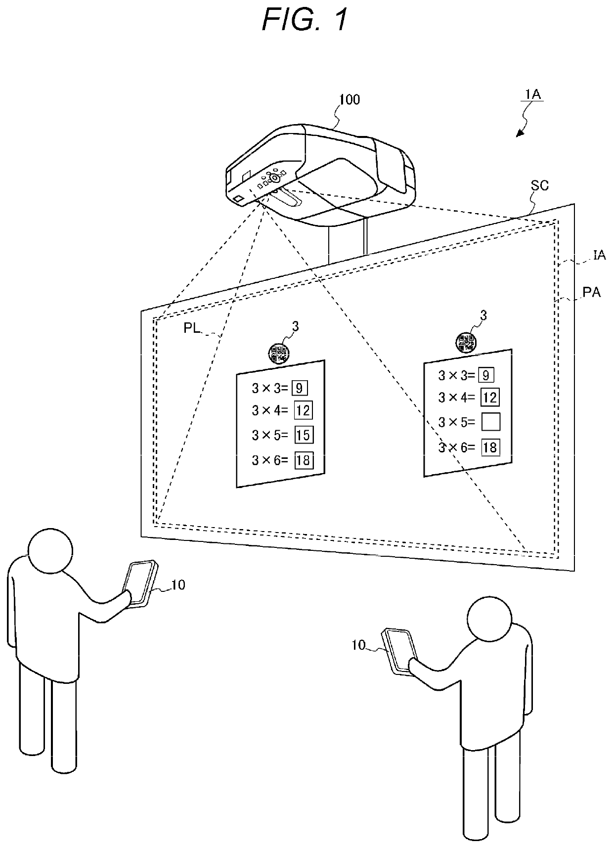
[0033]FIG. 1 is a perspective view of a display system 1A. The display system 1A includes a terminal apparatus 10 and a projector 100, which corresponds to an example of a display apparatus. The terminal apparatus 10 associates marker information 33, which represents characteristics of a marker 3, with an image that is a display target to be displayed by the projector 100. The projector 100 detects the position and characteristics of the marker 3 disposed on a screen SC, which is a display surface, identifies an image associated by the terminal apparatus 10 based on the characteristics of the detected marker 3, and displays the identified image in a position corresponding to the marker 3.

[0034]The position and shape of the marker 3 are optically detectable on the screen SC. FIG. 1 shows an example in which two markers 3 are disposed on the screen SC, but the number of markers 3 usable in the display system 1A is not limited to two and may instead be one ...

second embodiment

[0164]FIG. 9 shows the system configuration of a display system 1B according to a second embodiment.

[0165]The display system 1B according to the second embodiment includes a server apparatus 200 in addition to the terminal apparatus 10 and the projector 100. In the second embodiment, the server apparatus 200 corresponds to the “storage.”

[0166]The terminal apparatus 10 and the projector 100 are communicably coupled to the server apparatus 200. For example, the projector 100, the terminal apparatus 10, and the server apparatus 200 may be coupled to a single Wi-Fi access point. Wi-Fi is a registered trademark. Instead, the server apparatus 200 may be disposed as a component coupled to a communication network, such as the Internet, and the terminal apparatus 10 and the projector 100 may access the server apparatus 200 over the communication network.

[0167]In the second embodiment, the terminal apparatus 10 transmits the registration information containing the image data 31, the marker in...


PUM


Abstract

A terminal apparatus acquires marker information representing the characteristics of a marker and generates association information that associates a display target image with the marker information. A projector detects the position and characteristics of the marker disposed on a screen, identifies an image associated with the marker based on the marker information corresponding to the characteristics of the detected marker and the association information, determines the position where the image is displayed based on the position of the detected marker, and displays the identified image in the determined display position.

Description

[0001]The present application is based on, and claims priority from JP Application Serial Number 2019-032414, filed Feb. 26, 2019, the disclosure of which is hereby incorporated by reference herein in its entirety.BACKGROUND1. Technical Field[0002]The present disclosure relates to a display method and a display system.2. Related Art[0003]There has been a known method for detecting a marker disposed on a display surface and displaying an image associated with the detected marker.[0004]For example, in an image display apparatus disclosed in JP-A-2007-11276, a camera captures an image of an object disposed on a projection surface on which an image is projected, and an object ID that identifies the object is extracted from the resultant captured image data, followed by acquisition of information on an attribute of the object associated with the extracted object ID. The image display apparatus further generates an image to be projected on the projection surface based on the acquired attr...

Claims


Application Information

Patent Timeline
IPC IPC(8): H04N9/31G06F3/042
CPCH04N9/3182H04N9/3194G06F3/0425H04N9/3141H04N9/3179H04N21/43637H04N21/4122H04N21/4126H04N9/3185H04N9/3188
Inventor TANAKA, MASAKO
Owner SEIKO EPSON CORP
Features
  • Generate Ideas
  • Intellectual Property
  • Life Sciences
  • Materials
  • Tech Scout
  • Unparalleled Data Quality
  • Higher Quality Content
  • 60% Fewer Hallucinations
Learn More