Supercharge Your Innovation With Domain-Expert AI Agents!

Remote Release Buckle

a buckle and release technology, applied in the field of safety belts and harnesses, can solve the problems of not always convenient or even possible, the buckle the harness requires releasing but is not immediately accessible,

Active Publication Date: 2020-12-24
SMITH JASON +2
View PDF0 Cites 0 Cited by
  • Summary
  • Abstract
  • Description
  • Claims
  • Application Information

AI Technical Summary

Benefits of technology

The invention is a buckle-style fitting that includes a housing, a locking bar, and a latch. The latch can be inserted and released easily using a cord attached to the locking bar. The buckle can be quickly released by pulling on the cord or cable from either a near or far distance. Additionally, the buckle is designed to prevent accidental release during crashes or falls.

Problems solved by technology

There are often instances where a harness requires releasing but are not immediately accessible.
Releasing animal leashes from collars generally require a handler to reach to a buckle attached to the collar, which is not always convenient or even possible.
In some instances, it may be difficult for the occupant or rescue personnel to reach the buckle.

Method used


Image

  • Remote Release Buckle
  • Remote Release Buckle
  • Remote Release Buckle

Examples


first embodiment

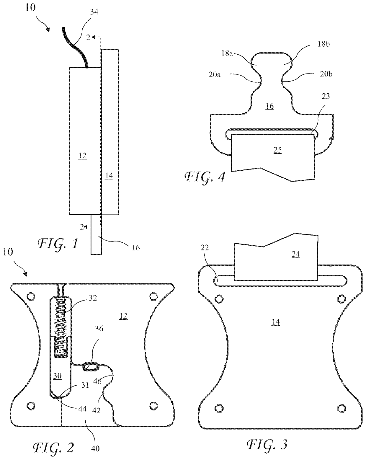
[0040]A side view of a remotely releaseable buckle assembly 10 according to the present invention is shown in FIG. 1. The buckle assembly 10 includes a major housing portion 12 and a housing cover 14. A keyed flat latch 16 is inserted into the buckle assembly 10 and a release cord or cable or trigger 34 extends out of the buckle assembly 10 for releasing the latch 16.

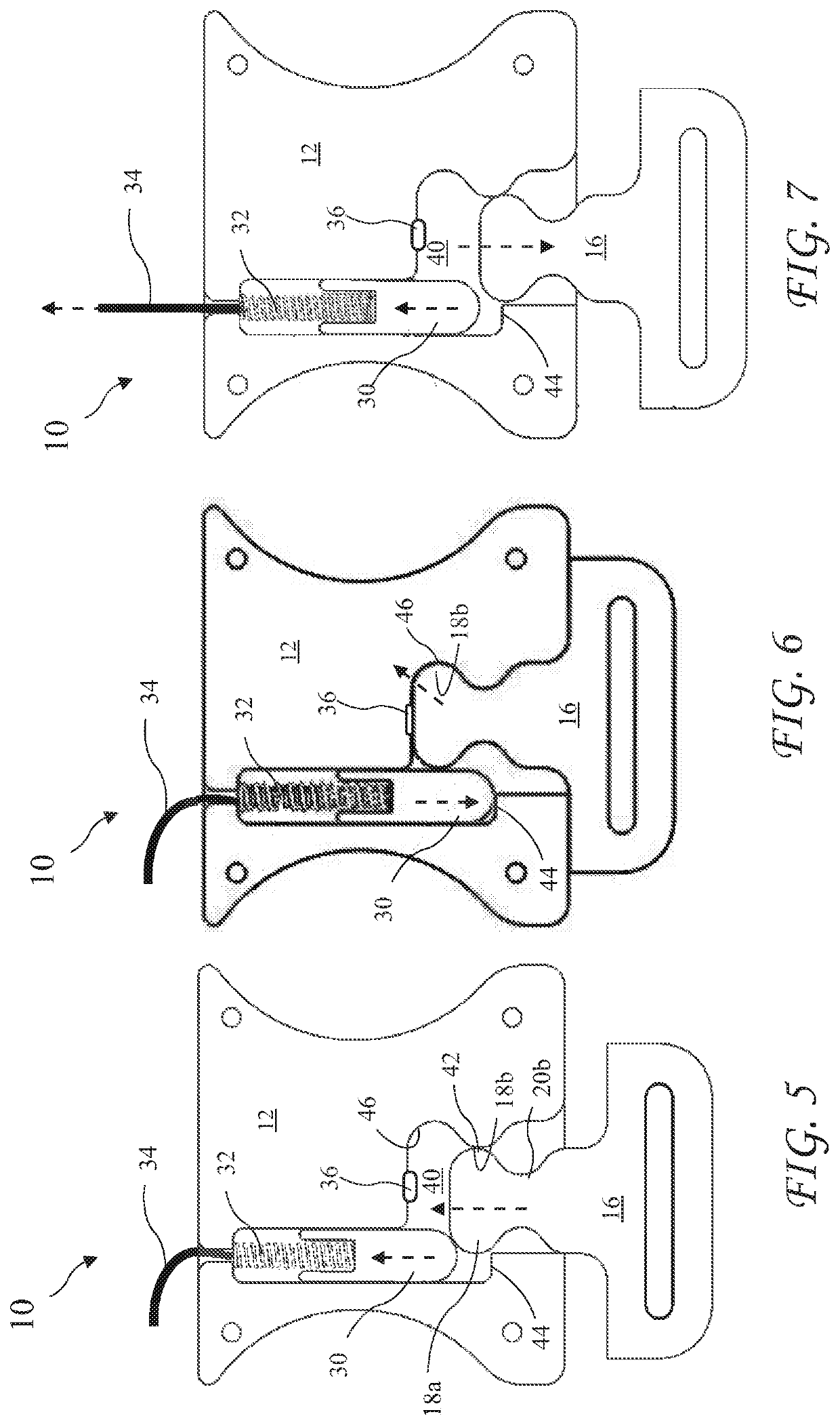
[0041]A front view of the major housing 12 is shown in FIG. 2 taken along line 2-2 of FIG. 1. The major housing portion 12 contains a sliding blocking bar 30, a compression spring 32 pressing the blocking bar 30 into the major housing portion 12. A latch cavity 40 receives the keyed flat latch 16 and a release spring 36 pushes down on the keyed flat latch 16 when residing in the latch cavity 40. The blocking bar 30 includes a tapered or rounded nose 31 and the latch cavity 40 includes an interior rounded bump 42 facing the blocking bar 30 and an interior corner 44 under the blocking bar 30.

[0042]A front view of the hous...

second embodiment

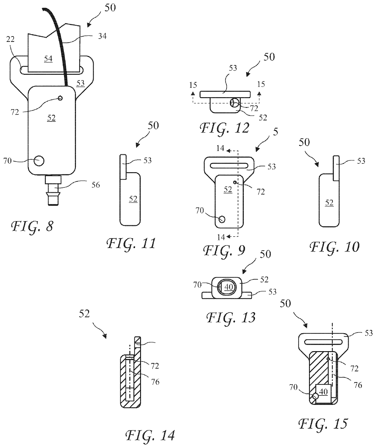
[0047]A front view of the invention is a remotely releaseable buckle assembly 50 shown in FIG. 8. The buckle assembly 50 includes a housing 52, a leash plate 53, a bar pin 72, a latch block 70, a cord 34, and a leash 54 through a slot 22 engaging the leash plate 53. A circular cross-section latch 56 is released by pulling the cord 34. The circular cross-section latch 56 may be attached to an animal collar and the cord 34 may be retained to run along the leash 54 allowing a user holding the leash to release the circular cross-section latch 56 by pulling the cord 34. The latch block 70 is preferably a cylindrical rod pressed into the housing

[0048]A front view of the housing 52 of the buckle assembly 50 is shown in FIG. 9, a left side view of the housing 52 is shown in FIG. 10, a right side view of the housing 52 is shown in FIG. 11, a top view of the housing 52 is shown in FIG. 12, and a bottom view of the housing 52 is shown in FIG. 13. The leash plate 53 is attached to the housing 5...


PUM


Abstract

A buckle assembly includes a housing enclosing a locking bar for securing a latch. The latch is inserted into a latch cavity of the buckle assembly, pushing the spring-loaded locking bar into the housing until a convex feature of the latch passes a convex feature of the latch cavity, and slides to the side, whereupon the locking bar is extended by a compression spring, thereby locking the latch from release from the buckle assembly. The latch is released from the latch cavity by pulling a release cord or cable or trigger attached to the locking bar to overcome the spring tension and draw the locking bar up, thus allowing the latch to move away from the convex feature of the latch cavity and release from the buckle assembly.

Description

CROSS-REFERENCE TO RELATED APPLICATIONS[0001]The present application claims the priority of U.S. Provisional Patent Application Ser. No. 62 / 864,053 filed Jun. 20, 2019, which application is incorporated in its entirety herein by reference.BACKGROUND OF THE INVENTION[0002]The present invention relates to safety belt and harness releases and in particular to a remotely released harness.[0003]There are often instances where a harness requires releasing but are not immediately accessible. Releasing animal leashes from collars generally require a handler to reach to a buckle attached to the collar, which is not always convenient or even possible. Merely releasing the leash results in the animal dragging the leash along with the animal, allowing the leash to be snagged by objects along the animal's path.[0004]Vehicles generally include a belt or harness for restraining motion of occupants. The belts or harness generally include a buckle to retain individual elements, and the buckle must b...

Claims


Application Information

Patent Timeline
IPC IPC(8): A01K27/00
CPCA01K27/005A01K27/003A44B11/253
Inventor SMITH, JASONHAWKINS, PHILIP J.HEDDY, GEORGE
Owner SMITH JASON
Features
  • R&D
  • Intellectual Property
  • Life Sciences
  • Materials
  • Tech Scout
  • Unparalleled Data Quality
  • Higher Quality Content
  • 60% Fewer Hallucinations
Learn More