Supercharge Your Innovation With Domain-Expert AI Agents!

Appliance stabilizing device with quick release attachment

a technology of a stabilizing device and an attachment device, which is applied in the direction of lighting and heating apparatus, household stoves or ranges, heating types, etc., can solve the problems of devices that cannot allow a tip-over and the vulnerability of the device, so as to improve the probability of the appliance not slipping, facilitate installation, and provide stability

Inactive Publication Date: 2011-03-01
LOWENSTEIN JR ARNOLD G
View PDF10 Cites 2 Cited by
  • Summary
  • Abstract
  • Description
  • Claims
  • Application Information

AI Technical Summary

Benefits of technology

"The present invention is a device for securing an appliance in position against a supporting surface. The device includes brackets and elongated members that are selectively attachable to the appliance. The elongated members have apertures spaced a distance from the brackets, with the fastener used to attach the appliance to the wall being positioned in the aperture. The elongated members are attached to the appliance at a point near the base of the appliance, and the fastener passes through the wall or the sole-plate of the wall. The elongated members have a triangular configuration, with the brackets having three apertures that form a triangle. The use of an attachment arm, pivotal with respect to the bracket, allows for self-adjustment of the appliance in relation to the point of attachment to the wall, making it easier to install the appliance and ensuring stability against tipping forces. The brackets and elongated members are made of high-strength materials, such as metallic or composite materials. The device allows for some movement in and out of the major plane of the bracket, but does not allow for movement along the length of the elongated members after attachment to the appliance. The pivotal attachment between the brackets and the elongated members includes a quick-release mechanism, allowing for easy detachment of the appliance from the wall without tools."

Problems solved by technology

In addition, when there is a possibility of earthquake at the location where the appliance is being used, it becomes critical that the appliance securing device handle the load which may be applied to the securing device in the event of an earthquake.
This could easily occur in the event of an earthquake or if the range was moved accidentally, leaving the appliance vulnerable to a tip-over.
Our device will not allow this to occur, unless it is manually released using the quick-release method during service, replacement or emergency removal.

Method used


Image

  • Appliance stabilizing device with quick release attachment
  • Appliance stabilizing device with quick release attachment
  • Appliance stabilizing device with quick release attachment

Examples


Embodiment Construction

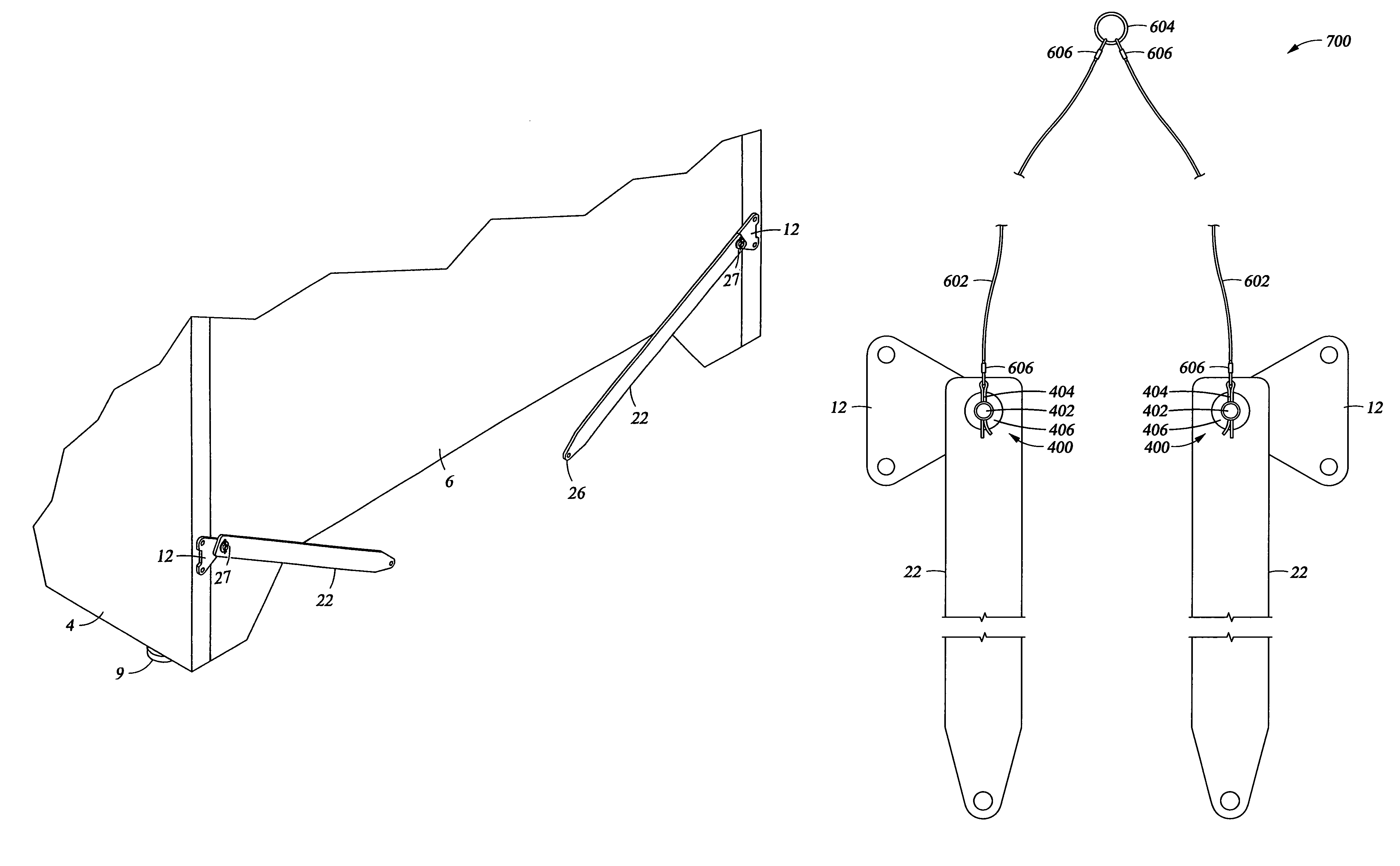
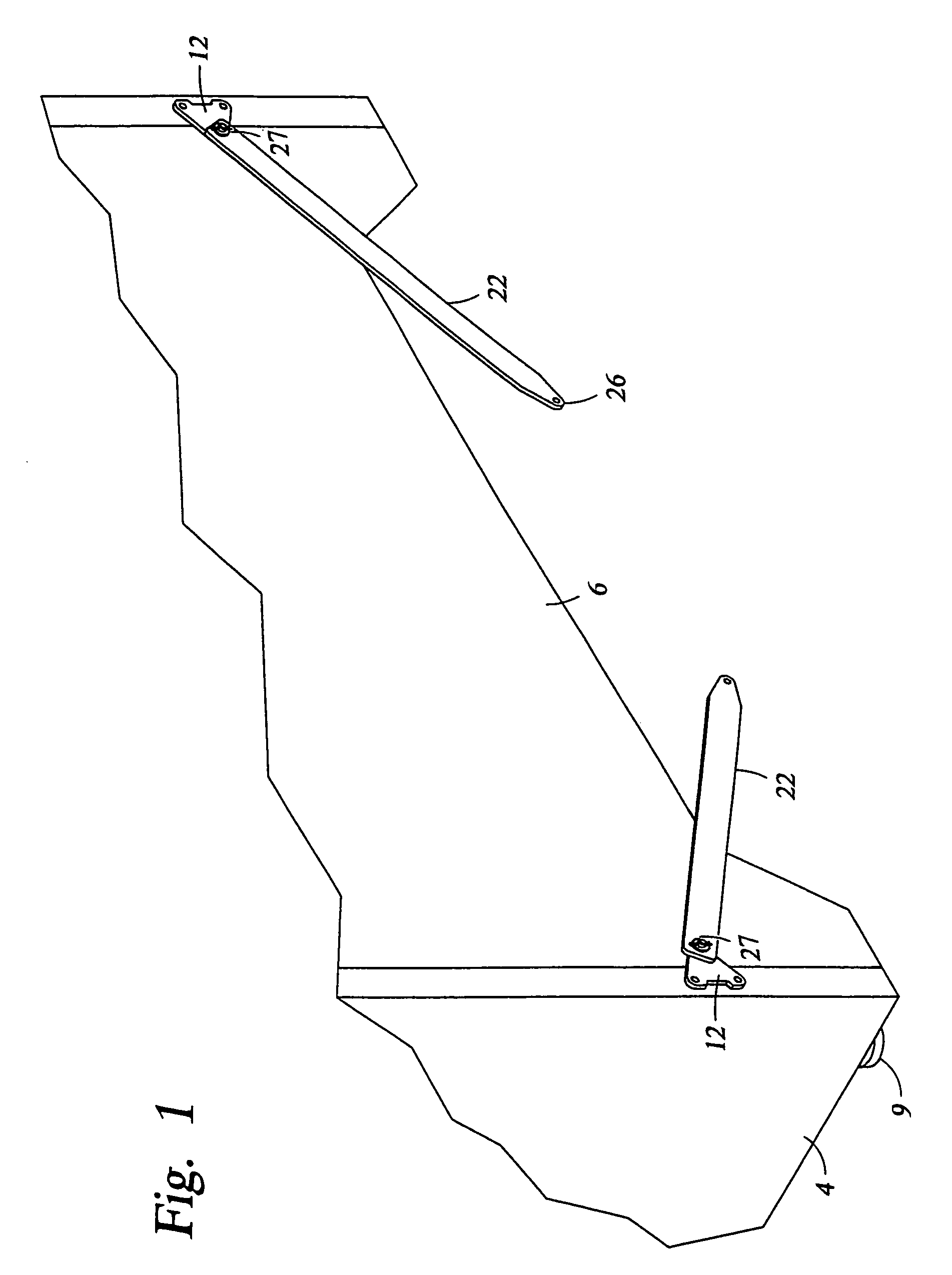
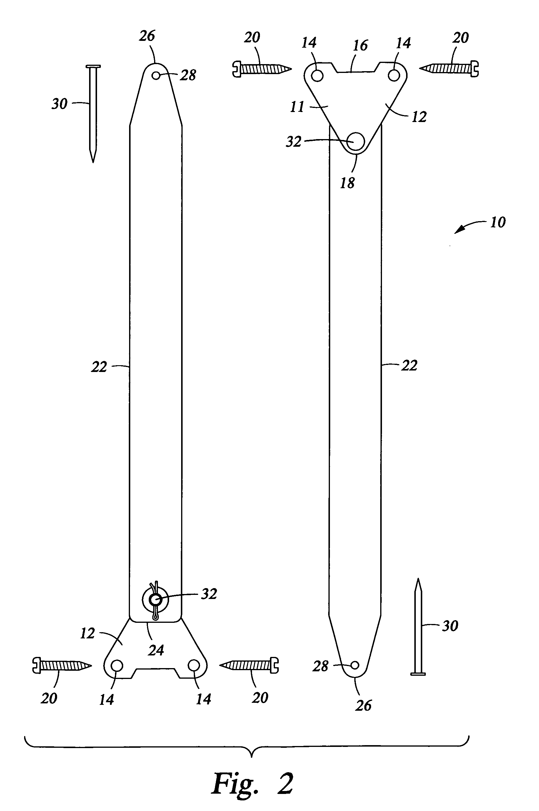
[0030]With reference now to the drawings, and in particular to FIGS. 1 through 8, a new appliance securing member embodying the principles and concepts of the present invention and generally designated by the reference numeral 10 will be described.

[0031]As best illustrated in FIGS. 1 through 3, the appliance stabilizing device 10 generally comprises at least two brackets 12. Each of the brackets includes a plate 11. The plate 11 of bracket 12 has at least three apertures 14 extending therethrough. The apertures 14 are spaced from each other to form a generally triangular configuration, or another configuration providing stability at least equal to that provided by the triangular configuration. One skilled in the art can envision a number of stable configurations, but a triangular configuration of the kind shown in FIGS. 1 and 2 is the simplest stable design. The plates 11 shown in FIGS. 1 and 2 are also triangular in configuration, but it is obvious to one of skill in the art that i...


PUM


Abstract

An appliance stabilizing device which is useful in securing an appliance in position against a supporting structure surface. The device includes a plurality of brackets which are selectively positionable on an appliance, with a plurality of elongated members, each pivotally attached to a bracket. Each elongated member has at least one aperture spaced a distance along the length of the elongated member from the pivotal point with the bracket. The elongated member is attached to a support surface, frequently a bottom plate or sole pate of the wall. The bracket includes apertures spaced from each other in a generally triangular configuration or a configuration of equivalent strength. The elongated member is typically pivotally attached at the apex of a generally triangular configuration of apertures. The device is self adjusting during attachment of the appliance to a supporting structure. An advantageous embodiment includes a quick-release mechanism at the pivotal attachment between the brackets and the first ends of the elongate members.

Description

[0001]The present application is a continuation-in-part of application Ser. No. 10 / 954,938 filed Sep. 30, 2004, titled: “Appliance Stabilizing Device”, which issued as U.S. Pat. No. 7,185,872 on Mar. 6, 2007, which is a continuation-in-part application of Ser. No. 10 / 389,029, filed Mar 17, 2003, titled: “Appliance Stabilizing Device”, which was abandoned in favor of application Ser. No. 10 / 954,938.BACKGROUND OF THE INVENTION[0002]1. Field of the Invention[0003]The present invention relates to appliance securing members and more particularly pertains to a new appliance securing member for selectively securing an appliance to a wall, to prevent the tipping of the appliance.[0004]2. Description of the Background Art[0005]The use of appliance securing members is known in the art. U.S. Pat. No. 5,076,525 describes a pair of brackets, one attached to the appliance and one to a wall, which brackets are coupled together to prevent tipping of the appliance. U.S. Pat. No. 4,754,948 describes ...

Claims


Application Information

Patent Timeline
Patent Type & Authority Patents(United States)
IPC IPC(8): A47G1/16F24C15/08
CPCA47B97/00F24C15/083A47B2097/008
Inventor LOWENSTEIN, JR., ARNOLD G.
Owner LOWENSTEIN JR ARNOLD G
Features
  • R&D
  • Intellectual Property
  • Life Sciences
  • Materials
  • Tech Scout
  • Unparalleled Data Quality
  • Higher Quality Content
  • 60% Fewer Hallucinations
Learn More