Wire-wound inductor component

a technology of inductor components and wires, which is applied in the direction of inductances, inductances with magnetic cores, basic electric elements, etc., can solve the problems of high molding difficulty of cover members, difficulty in achieving height reduction, and height reduction, so as to achieve height and size reduction

Pending Publication Date: 2020-12-24
MURATA MFG CO LTD
View PDF15 Cites 0 Cited by
  • Summary
  • Abstract
  • Description
  • Claims
  • Application Information

AI Technical Summary

Benefits of technology

[0009]Accordingly, the present disclosure provide a wire-wound

Problems solved by technology

Further, when the terminal electrode is brought into contact with a wire wound around the shaft portion, there is a possibility that a short circuit or the like may occur, and therefore, it is necessary to secure a certain distance or more between the terminal electrode and the shaft portion.
Since this value of a certain level or more is determined irrespective of a dimension of the core, for example, it may be a major obstacle for achieving a reduction in height of the core, such as a height dimension of equal to or less than about 0.5 mm.
On the other hand, in this case, it is necessary t

Method used


Image

  • Wire-wound inductor component
  • Wire-wound inductor component
  • Wire-wound inductor component

Examples


Embodiment Construction

[0022]Hereinafter, an embodiment will be described.

[0023]It should be noted that the accompanying drawings may illustrate by enlarging constituent elements in order to facilitate understanding. The dimensional ratio of the constituent elements may be different from actual one or may differ from that in other figures. Although hatching is used in the cross-sectional view, hatching of some constituent elements may be omitted for ease of understanding.

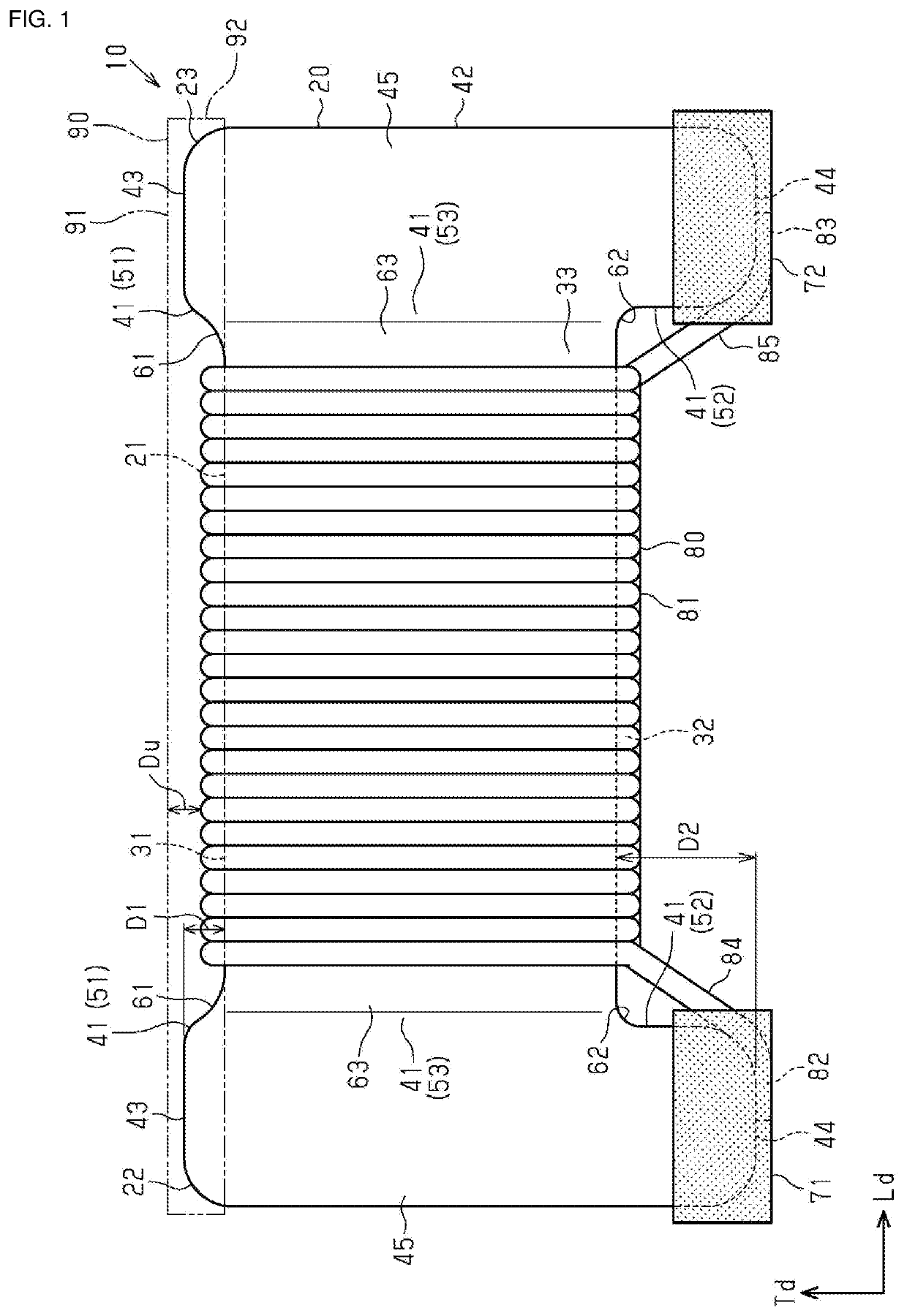
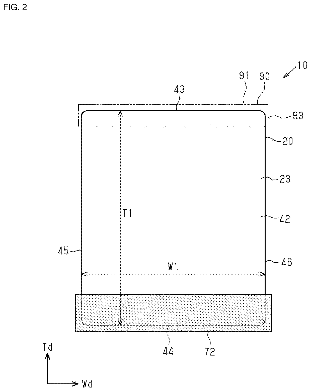
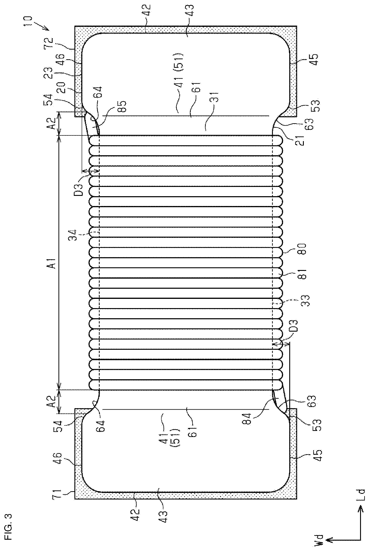
[0024]A wire-wound inductor component 10 illustrated in FIG. 1, FIG. 2, FIG. 3, and FIG. 4 is a surface-mounted component mounted on, for example, a circuit board or the like. The wire-wound inductor component 10 may be used in a variety of devices including, for example, portable electronic devices (mobile electronic devices) such as smart phones or mobile electronic devices (e.g., smart watches) for wrist donning.

[0025]The wire-wound inductor component 10 includes a core 20, a first terminal electrode 71, a second terminal electrode 72,...


PUM


Abstract

A wire-wound inductor component includes a core having a columnar shaft portion, first and second support portions provided on first and second end portions of the shaft portion, first and second terminal electrodes provided on the respective support portions, a wire wound around the shaft portion, and a cover member covering an upper surface of the shaft portion. In a height direction of the core, a distance between an upper surface and a top surface of the support portions is a top surface step, and a distance between a lower surface of the shaft portion and a bottom surface of the support portions is a bottom surface step. The top surface step is smaller than the bottom surface step and larger than a wire diameter, and a distance between the upper surface and an uppermost surface of the wire is larger than half of the top surface step.

Description

CROSS-REFERENCE TO RELATED APPLICATION[0001]This application claims benefit of priority to Japanese Patent Application No. 2019-115388, filed Jun. 21, 2019, the entire content of which is incorporated herein by reference.BACKGROUNDTechnical Field[0002]The present disclosure relates to a wire-wound inductor component.Background Art[0003]Existing various types of inductor components are mounted on an electronic apparatus. A wire-wound inductor component includes a core and a wire wound around the core. The core includes a shaft portion around which a wire is wound, and a first support portion and a second support portion that are respectively provided at both ends of the shaft portion and that protrude in a direction intersecting with an axial direction of the shaft portion. A terminal electrode is formed on each bottom surface of the first support portion and the second support portion, as described, for example, in Japanese Unexamined Patent Application Publication No. 2017-163099)....

Claims


Application Information

Patent Timeline
IPC IPC(8): H01F27/28H01F27/24H01F27/29
CPCH01F27/29H01F27/2823H01F27/24H01F17/04H01F27/02H01F27/292H01F17/045
Inventor TANAKA, AKIRANOYA, SUNAOGOTOHDA, TOMOTAKA
Owner MURATA MFG CO LTD
Why Eureka
Try Eureka