Continuous positive airway pressure apparatus
- Summary
- Abstract
- Description
- Claims
- Application Information
AI Technical Summary
Benefits of technology
Problems solved by technology
Method used
Image

Examples
first embodiment
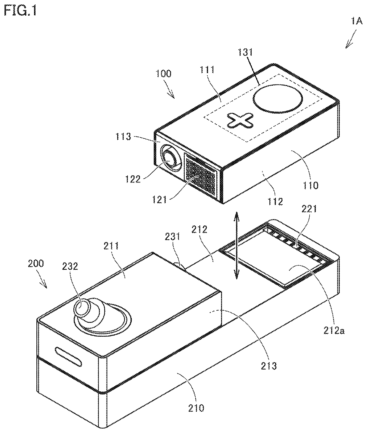
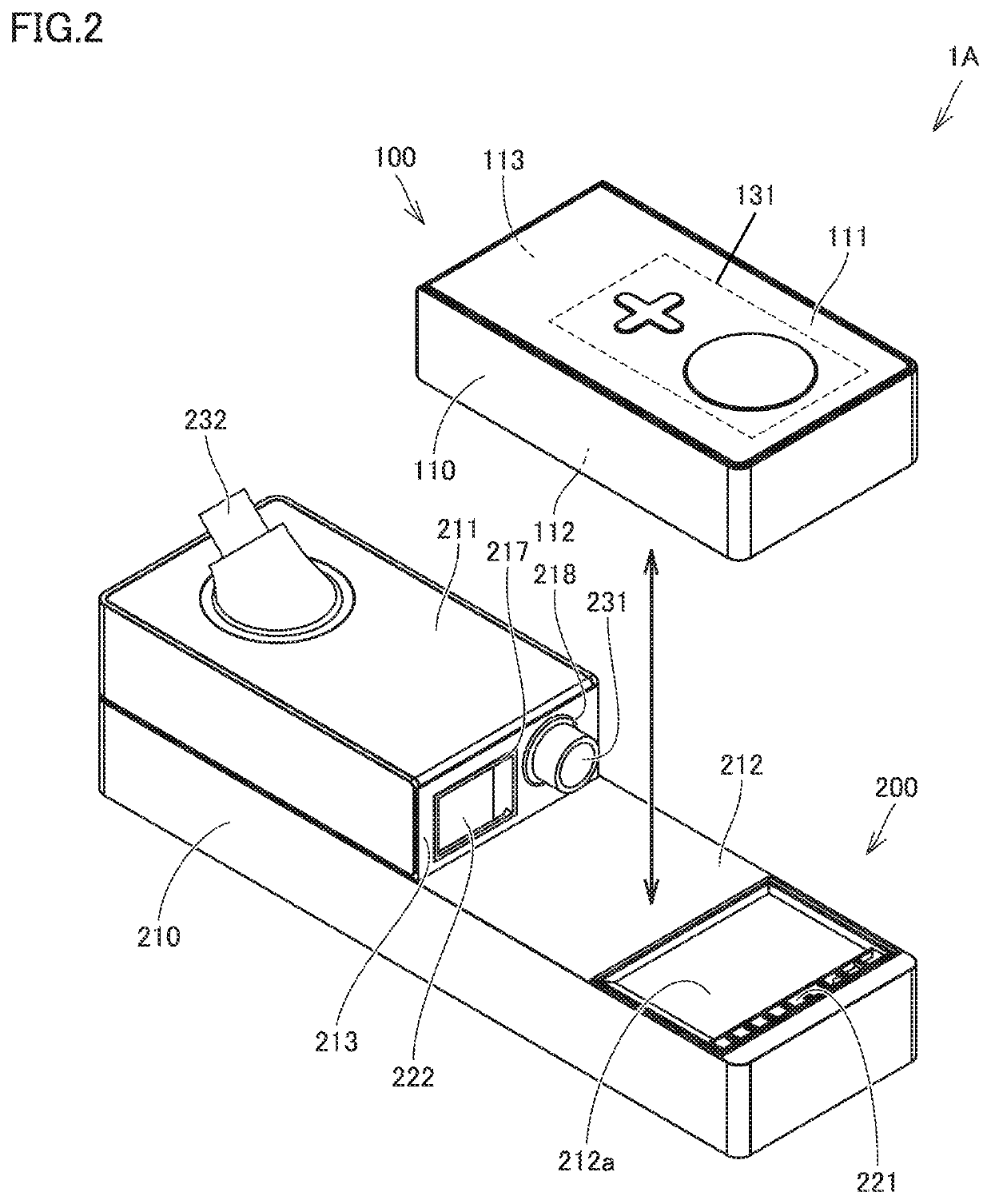
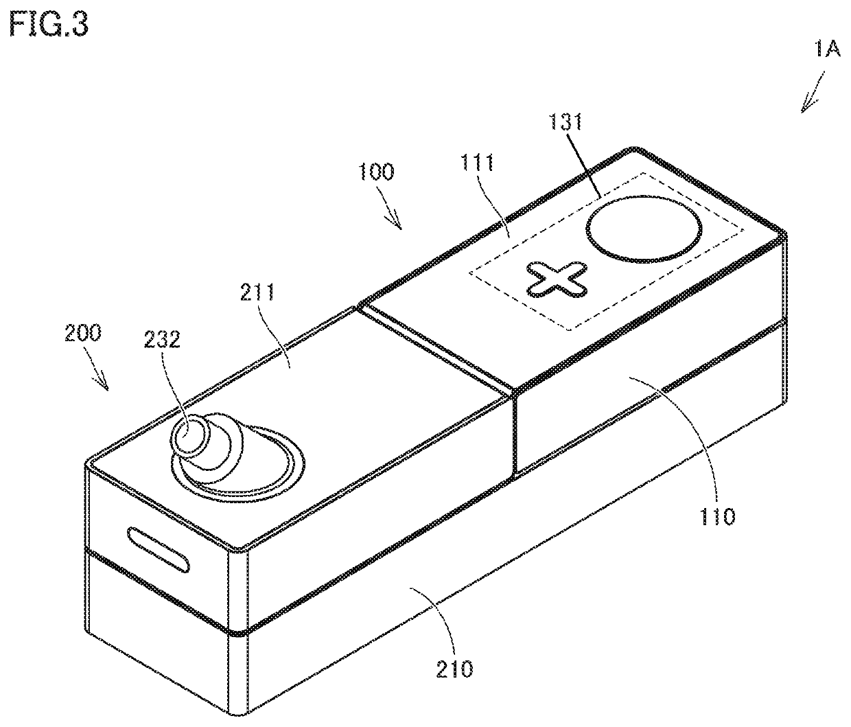
[0037]FIG. 1 is a perspective view showing a manner of attachment and detachment of a main body unit to / from a base unit of a CPAP apparatus according to the first embodiment of the present disclosure. FIG. 2 is another perspective view of the manner of attachment and detachment shown in FIG. 1 as seen from a different angle. FIG. 3 is a perspective view showing the state where the main body unit is attached to the base unit in the CPAP apparatus according to the present embodiment. First, referring to FIGS. 1 to 3, an explanation will be given with regard to a schematic configuration of a CPAP apparatus 1A according to the present embodiment and the manner of attachment and detachment thereof.
[0038]As shown in FIGS. 1 to 3, CPAP apparatus 1A includes a main body unit 100 as the first unit, and a base unit 200 as the second unit. In this case, main body unit 100 mainly includes an air blower 140 and a first silencer 150 (see FIG. 5 to FIG. 9 and FIG. 12 and so on). Base unit 200 mai...
second embodiment
[0130]FIG. 13 is a perspective view showing the manner of attachment and detachment between a main body unit, a base unit, and an additional base unit of a CPAP apparatus according to the second embodiment of the present disclosure. In the following, a CPAP apparatus 1B according to the second embodiment will be described with reference to FIG. 13.
[0131]As shown in FIG. 13, CPAP apparatus 1B includes a main body unit 100 as the first unit, a base unit 200 as the second unit, and an additional base unit 500 as the third unit.
[0132]Main body unit 100 is the same as that in the above-mentioned first embodiment. On the other hand, base unit 200 is different from that in the above-mentioned first embodiment and mainly includes second flow path 220 and second silencer 240, but does not include third flow path 230 and humidifying mechanism 250. Furthermore, additional base unit 500 mainly has a third flow path 530 and a humidifying mechanism 550.
[0133]In other words, CPAP apparatus 1B acco...
third embodiment
[0142]FIG. 14 is a partially cutaway plan view showing the state where a main body unit is attached to a base unit in a CPAP apparatus according to the third embodiment of the present disclosure. In the following, a CPAP apparatus 1C according to the present embodiment will be described with reference to FIG. 14.
[0143]As shown in FIG. 14, CPAP apparatus 1C has basically the same configuration as that in the above-described first embodiment, and includes main body unit 100 as the first unit and base unit 200 as the second unit. Main body unit 100 includes air blower 140 and first silencer 150. Base unit 200 includes a second silencer (that is the same as second silencer 240 shown in FIG. 11 and the like) and a humidifying mechanism (that is the same as humidifying mechanism 250 shown in FIG. 9 and the like).
[0144]In this case, although no details will be explained for avoiding repeated explanations, CPAP apparatus 1C according to the present embodiment can also take two types of use ...
PUM
 Abstract
Description
Claims
Application Information
 - Generate Ideas
- Intellectual Property
- Life Sciences
- Materials
- Tech Scout
- Unparalleled Data Quality
- Higher Quality Content
- 60% Fewer Hallucinations
Browse by: Latest US Patents, China's latest patents, Technical Efficacy Thesaurus, Application Domain, Technology Topic, Popular Technical Reports.
© 2025 PatSnap. All rights reserved.Legal|Privacy policy|Modern Slavery Act Transparency Statement|Sitemap|About US| Contact US: help@patsnap.com