Power supply system and dc/dc converter

a power supply system and converter technology, applied in the direction of electric variable regulation, process and machine control, instruments, etc., to achieve the effect of high accuracy, advantageous in downsizing and simplification

Active Publication Date: 2021-01-07
SUMIDA CORP
View PDF0 Cites 0 Cited by
  • Summary
  • Abstract
  • Description
  • Claims
  • Application Information

AI Technical Summary

Benefits of technology

[0008]The present invention can provide a power supply system and a DC / DC converter that can synchronize a primary circuit and a secondary circuit with high accuracy and are advantageous in downsizing and simplification.

Problems solved by technology

This is disadvantageous in singly managing both of charge and discharge of a battery to downsize an apparatus as a whole and simplify its configuration.

Method used


Image

  • Power supply system and dc/dc converter
  • Power supply system and dc/dc converter
  • Power supply system and dc/dc converter

Examples


first modification

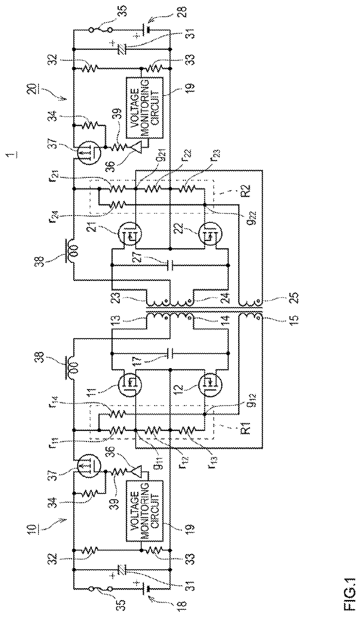
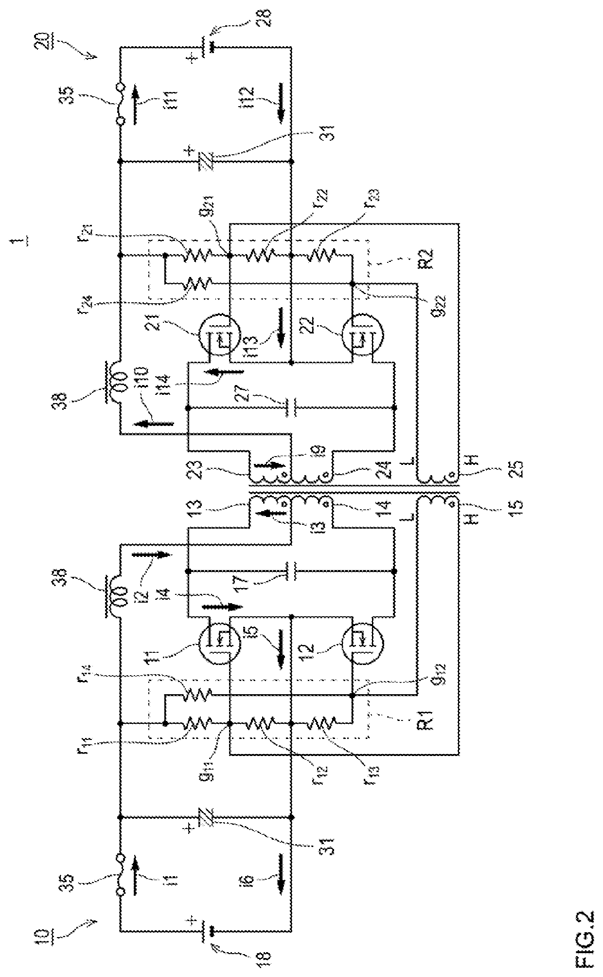
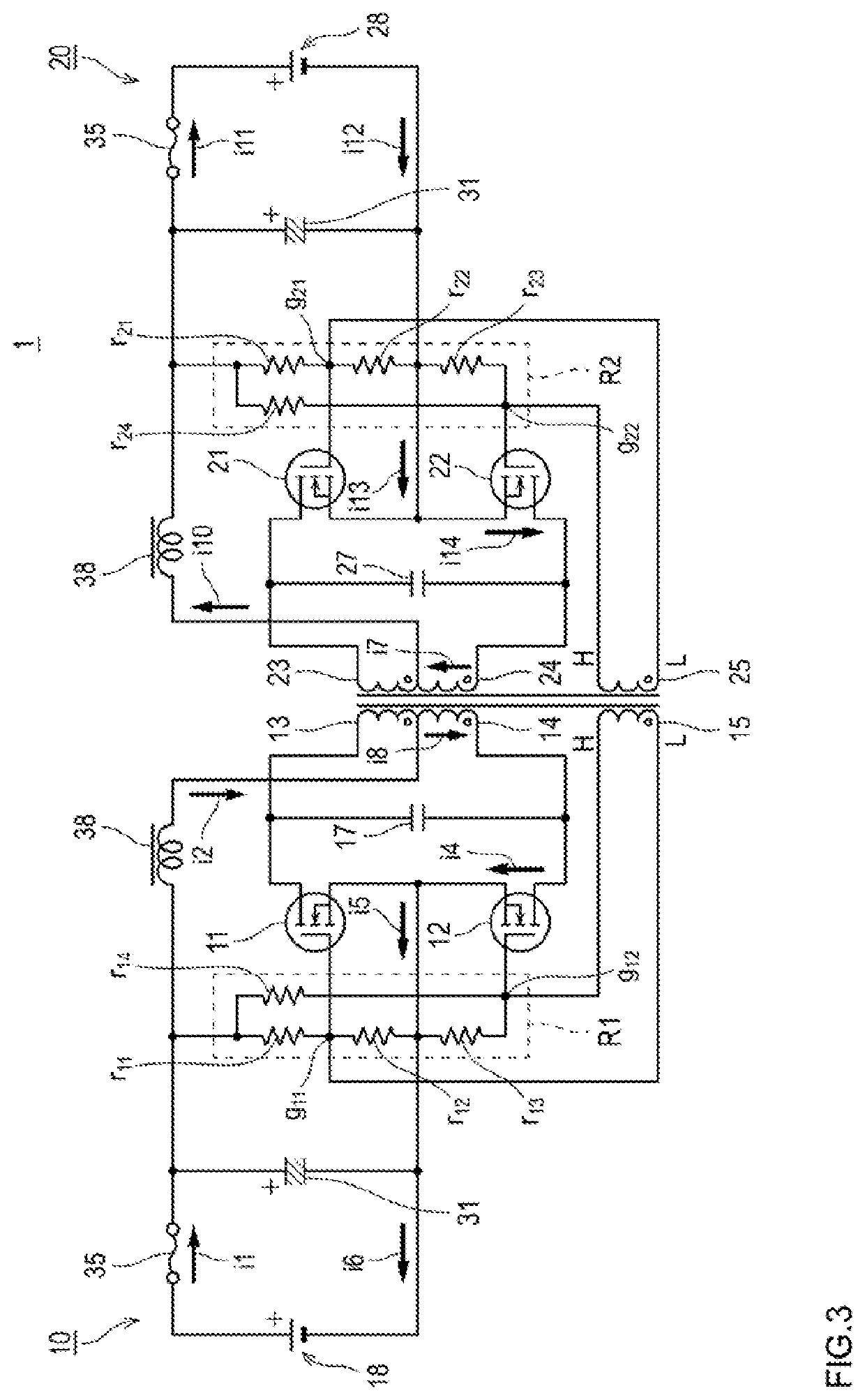
[0062]FIG. 6 illustrates a power supply system 2 in which a relay switch 67 replaces a transistor element to be used for monitoring a voltage in the manner described in the foregoing embodiment. As illustrated in FIGS. 1 and 6, as a component that disconnect the battery devices 18 and 28, any component that can monitor a voltage and disconnect the battery device 18 from the first circuit 10 and the battery device 28 from the second circuit 20 quickly when abnormality occurs in the first circuit 10 or the second circuit 20, can be used. Further, different components may be used in the first circuit 10 and the second circuit 20, respectively. Moreover, the power supply system according to the embodiment is not limited to a configuration in which such component is provided in each of the first circuit 10 and the second circuit 20, and the component may be provided only in one of the circuits that has a risk of abnormality occurrence.

second modification

[0063]Further, the power supply system according to the embodiment is not limited to a configuration in which the first circuit 10 and the second circuit 20 are provided in one-to-one correspondence, and a plurality of circuits may be provided on a secondary side. FIG. 7 is a diagram for explaining a power supply system 6 in which two circuits of the second circuit 20 and a third circuit 60 are provided on a secondary side in the power supply system 1 according to the above-described embodiment. The third circuit 60 is configured similarly to the first circuit 10 or the second circuit 20. Specifically, the third circuit 60 includes a battery device 68, resistance elements r61 to r64, transistor element 61 and 62, the capacitor 27, coil units 63 and 64, and a driving coil 65. Further, the third circuit 60 also includes a component that detects abnormality and disconnects the battery device 68 from the third circuit 60.

[0064]The third circuit 60 is caused to operate similarly to the s...


PUM


Abstract

A power supply system is provided that can synchronize a primary circuit and a secondary circuit with high accuracy and are advantageous in downsizing and simplification. The system includes a first circuit including: a battery device; transistor elements to which a voltage is supplied; coil units to which a feeding current is supplied in an on state of the transistor elements; a capacitor that changes a flow direction of the feeding current; and a driving coil that turns on/off the transistor elements, and a second circuit including: coil units and a driving coil in which induced electromotive force is generated; transistor elements that are turned on/off by the induced electromotive force; and a battery device that receives supply of power in an on state of the transistor elements.

Description

CROSS-REFERENCE TO RELATED APPLICATIONS[0001]This application claims the benefit of Japanese Patent Application No. 2019-125251 filed on Jul. 4, 2019 in the Japanese Patent Office, the disclosure of which is herein incorporated in its entirety by reference.BACKGROUNDTechnical Filed[0002]The present invention relates to a power supply system and a DC / DC converter.Related Art[0003]A bidirectional converter is known as a power conversion apparatus capable of singly performing both charge and discharge. Examples of such a bidirectional converter include a bidirectional DC / DC converter described in Japanese Laid-open patent publication No. 2011-234541. This DC / DC converter includes a primary circuit, a transformer, and a secondary circuit. Each of the primary circuit and the secondary circuit includes four reverse-conducting semiconductor switches forming a full bridge. Turn-on / off of those four semiconductor switches is controlled by a control circuit. The control circuit gives gate con...

Claims


Application Information

Patent Timeline
Patent Type & Authority Applications(United States)
IPC IPC(8): H02M3/335H02J7/00
CPCH02M3/33584H02J7/0063H02M3/33592H02J7/0068H02J2207/20H02J7/342H02M3/337H02M3/3382
Inventor MIYAZAKI, HIROYUKI
Owner SUMIDA CORP
Why Eureka
Try Eureka