Piezoelectric film sensor

Inactive Publication Date: 2010-10-07
AISIN SEIKI KK +1
View PDF6 Cites 23 Cited by
  • Summary
  • Abstract
  • Description
  • Claims
  • Application Information

AI Technical Summary

Benefits of technology

[0033]With this arrangement, in the case of providing the terminals of the signal electrode and the ground electrode i

Problems solved by technology

However, with the piezoelectric sensor disclosed in Patent Document 1, as its manufacture involves laminating a plurality of layers such as the piezoelectric film, the electrode layers, the shield layer, the bonding layer, the insulating layers, the manufacturing steps and costs are so increased that the making it as a commercial product was not feasible.
Further, a great a

Method used


Image

  • Piezoelectric film sensor
  • Piezoelectric film sensor
  • Piezoelectric film sensor

Examples


Example

First Embodiment

[0040]Next, a first embodiment of a piezoelectric film sensor relating to the present invention will be described with reference to FIGS. 1-4.

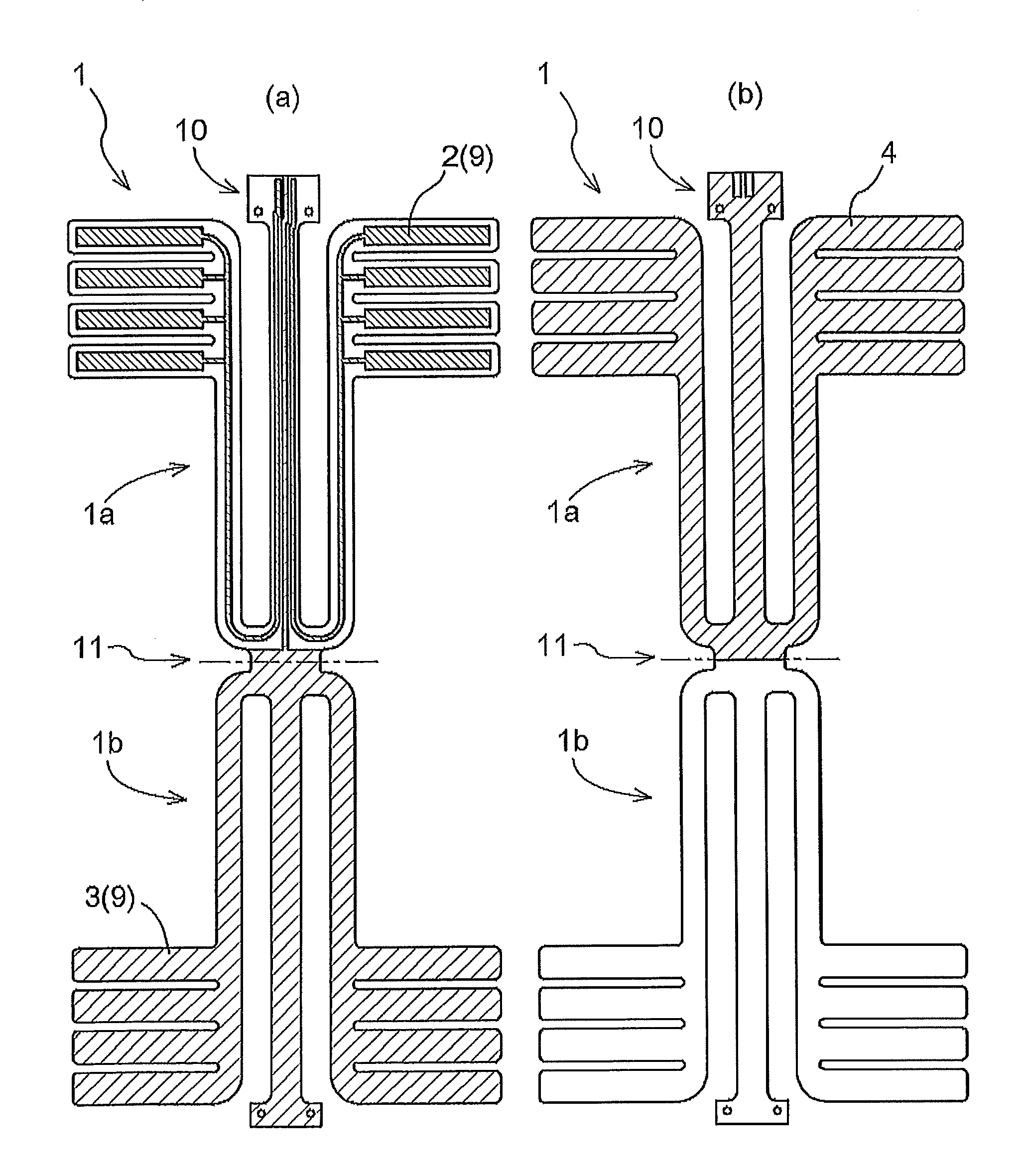
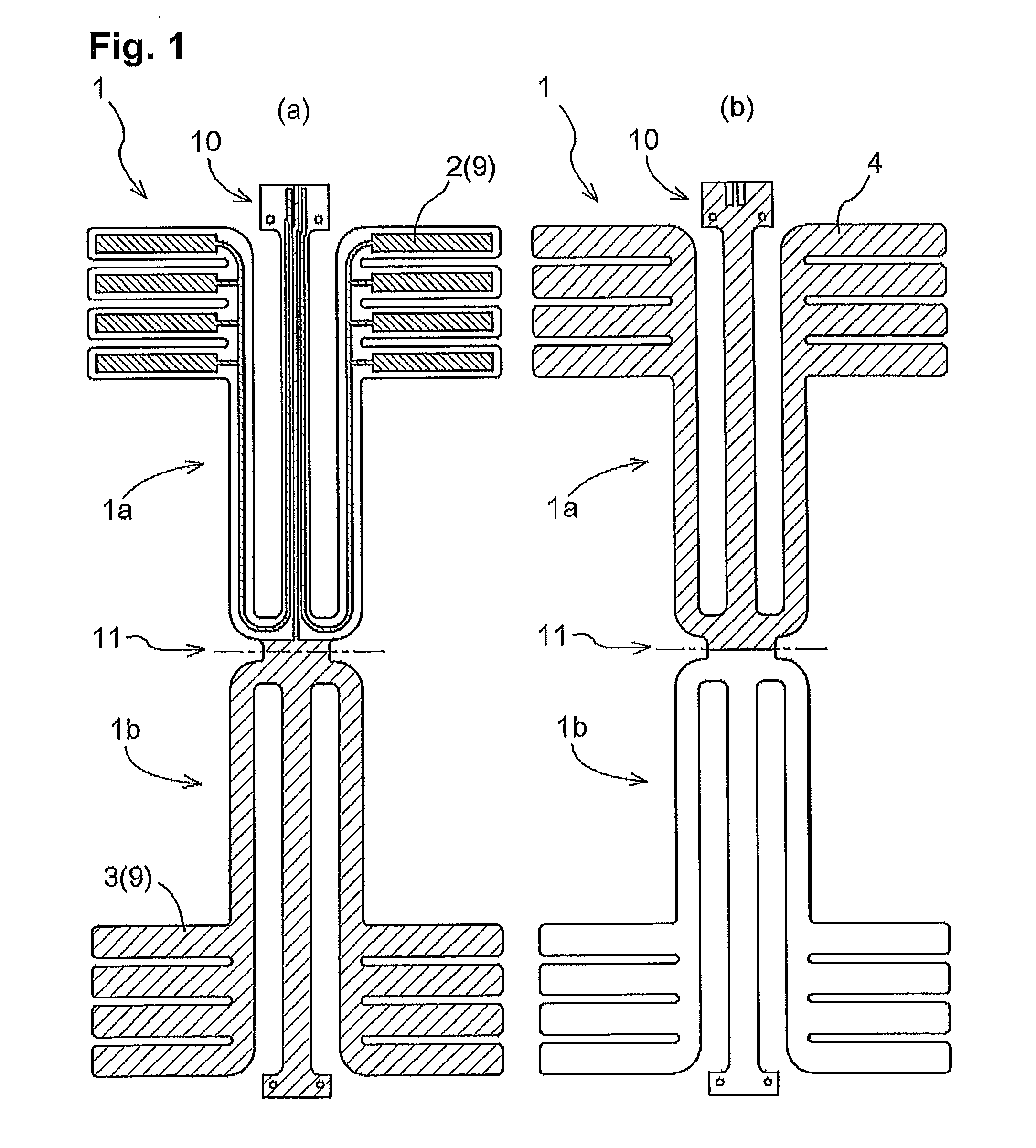
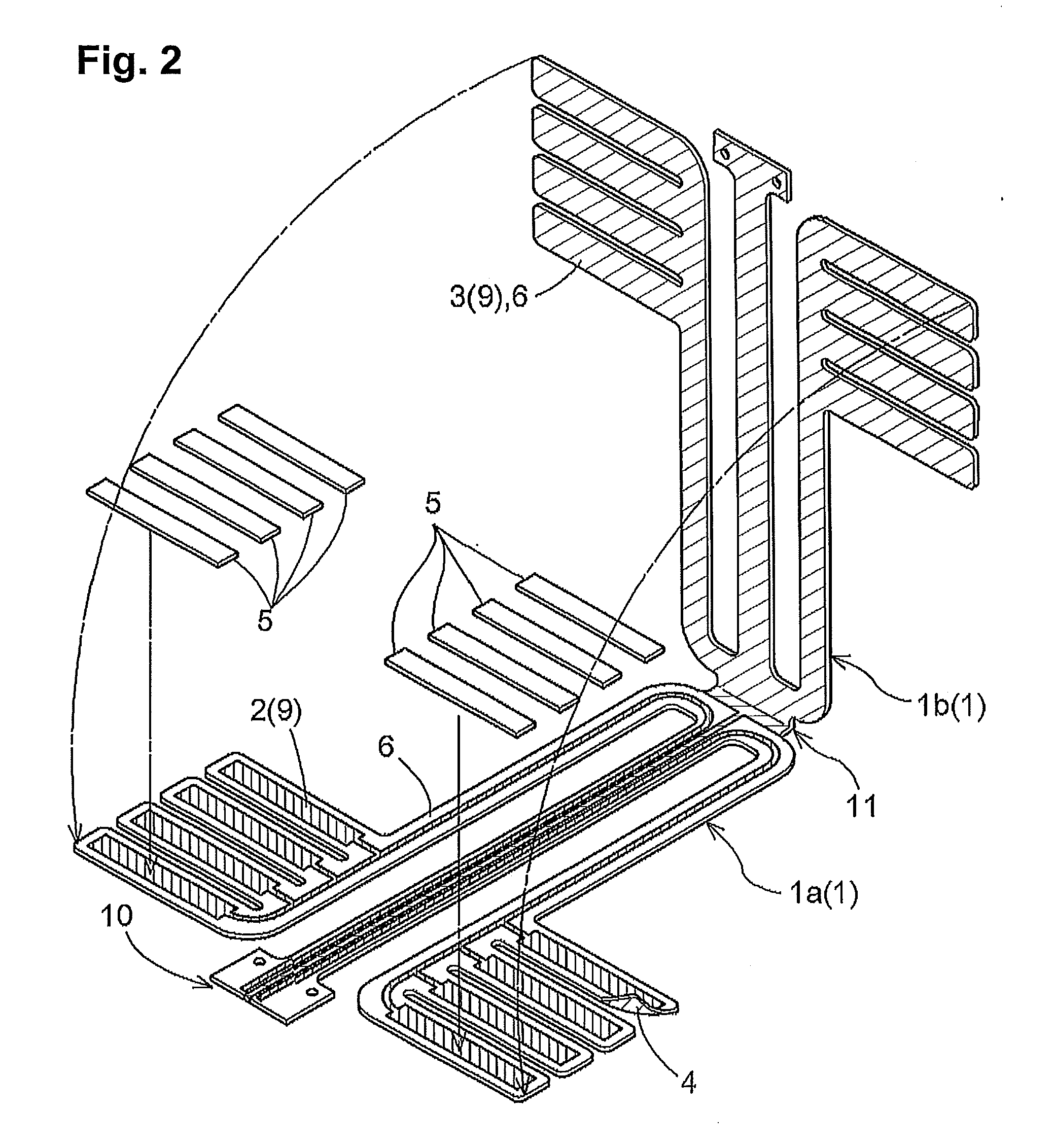
[0041]The piezoelectric film sensor relating to this embodiment includes a substrate 1 having a folded portion 11, a signal electrode 2 and a ground electrode 3 formed on a face of the substrate 1, a piezoelectric film 5 formed of polyvinylidene fluoride (PVDF), and a bonding layer 6 for bonding the substrate 1 as being folded.

[0042]The piezoelectric film 5 generates an electric charge by the piezoelectric effect. In operation, when an external force is applied to the piezoelectric film 5 to deform this film 5, an electric charge generated in this deformed piezoelectric film 5 can be obtained as an electric signal.

[0043]FIG. 1 are developments in a plane view showing the electrode pattern formed on the substrate 1 of the piezoelectric film sensor relating to this embodiment. FIG. 1 (a) shows a face (front surface) on one side o...

Example

Second Embodiment

[0057]Next, a second embodiment of the piezoelectric film sensor relating to the present invention will be described with reference to FIG. 5.

[0058]The piezoelectric film sensor relating to this embodiment, has a substantially same construction as the piezoelectric film sensor according to the first embodiment, but is distinguished therefrom in that the terminals 10 are provided at the folded portion 11 of the substrate 10.

[0059]FIG. 5 is a development in the plane view showing the electrode pattern formed on the substrate 1 of the piezoelectric film sensor according to this embodiment. In this embodiment, an angular hook-shape cutout 13 is formed from the center of the folded portion 11 toward the second substrate portion 1b. The signal electrode 2 extends beyond the folded portion 11 to the inside of the area delimited by the cutout 13. On the other hand, the ground electrode 3 is formed in the entire area of the second substrate portion 1b other than the area sep...

Example

Third Embodiment

[0063]Next, a third embodiment of the piezoelectric film sensor relating to the present invention will be described with reference to FIG. 6.

[0064]The piezoelectric film sensor relating to this embodiment, has a substantially same construction as the piezoelectric film sensor according to the first embodiment, but is distinguished therefrom in that the substrate 1 includes two folded portions 11, 12.

[0065]FIG. 6 is a development in a plane view showing electrode pattern formed on the substrate 1 of the piezoelectric film sensor according to the present embodiment. In this embodiment, the substrate 11, as being folded at the folded portions 11, 12, is sectioned into three areas (in this specification, these areas will be referred to as the “first substrate portion”, the “second substrate portion” and the “third substrate portion”, respectively). Here, the first substrate portion 1a and the second substrate portion 1b are sectioned from each other by the first folded p...


PUM


Abstract

A piezoelectric film sensor includes a substrate 1 having a signal electrode 2 and a ground electrode 3 formed on the surface thereof, the substrate being folded to cause the signal electrode 2 and the ground electrode 3 to be overlapped with each other in a plane view, a piezoelectric film 5 inserted between the signal electrode 2 and the ground electrode 3 formed on the substrate 1 and a bonding layer 6 for bonding the folded substrate 1 thereby to affix the signal electrode 2, the ground electrode 3 and the piezoelectric film 5 together.

Description

TECHNICAL FIELD[0001]The present invention relates to a piezoelectric film sensor having a piezoelectric film.BACKGROUND ART[0002]Conventionally, a piezoelectric sensor having a piezoelectric film formed of a polymer material, in particular, polyvinylidene fluoride (PVDF) is employed as a pressure sensor for determining presence / absence of a human, an animal, an object, etc. by detecting a load applied to an elastic support such as a bed, a mat, a sheet, etc. When the piezoelectric sensor is employed as such pressure sensor, in order to dispose the piezoelectric sensor precisely at the load detecting position in the support, the piezoelectric member is formed to suit its disposing shape relative to the support and then electrodes and wires are provided on its faces, thereby to complete the pressure sensor.[0003]According to one known example of such piezoelectric sensor, silver paste is applied to both faces (sides) of a piezoelectric film, so as to form one side as a signal electro...

Claims


Application Information

Patent Timeline
IPC IPC(8): H01L41/053G01L1/16H01L41/047
CPCG01L1/16
Inventor ANDO, MITSUHIROFUJIOKA, EIJIKOGURE, SHUNSUKETAKAYANAGI, HITOSHIMORIYAMA, NOBUHIROSUDO, RYUICHI
Owner AISIN SEIKI KK
Why Eureka
Try Eureka