Eureka AIR delivers breakthrough ideas for toughest innovation challenges, trusted by R&D personnel around the world.

Systems and processes for automated sand separation

Active Publication Date: 2021-03-18
CHEVROU USA INC
View PDF0 Cites 6 Cited by
  • Summary
  • Abstract
  • Description
  • Claims
  • Application Information

AI Technical Summary

Benefits of technology

The present invention provides an improved system for handling sand in oil and gas wells. The system minimizes labor and expenses and records data accurately, leading to improved well design and planning. It reduces sand production, well damage, and equipment corrosion due to sand. Overall, the system automates and integrates all aspects of sand handling, resulting in improved oil and gas production.

Problems solved by technology

Unfortunately, such systems are labor intensive and inaccurate as to amount of sand flowback and other parameters.

Method used


Image

  • Systems and processes for automated sand separation
  • Systems and processes for automated sand separation
  • Systems and processes for automated sand separation

Examples


specific embodiments

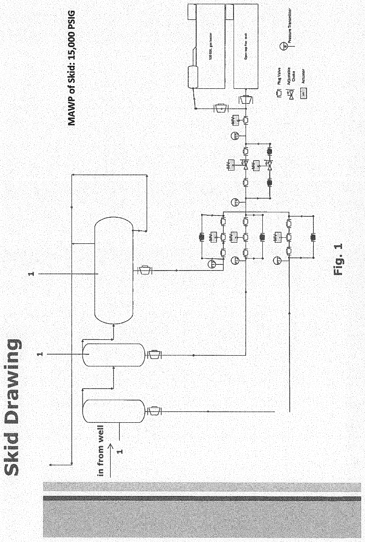
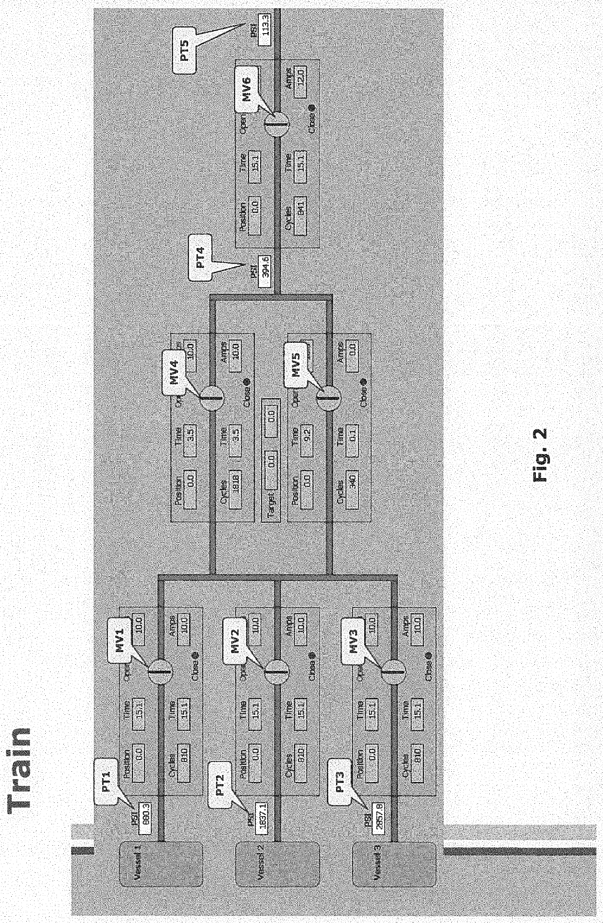
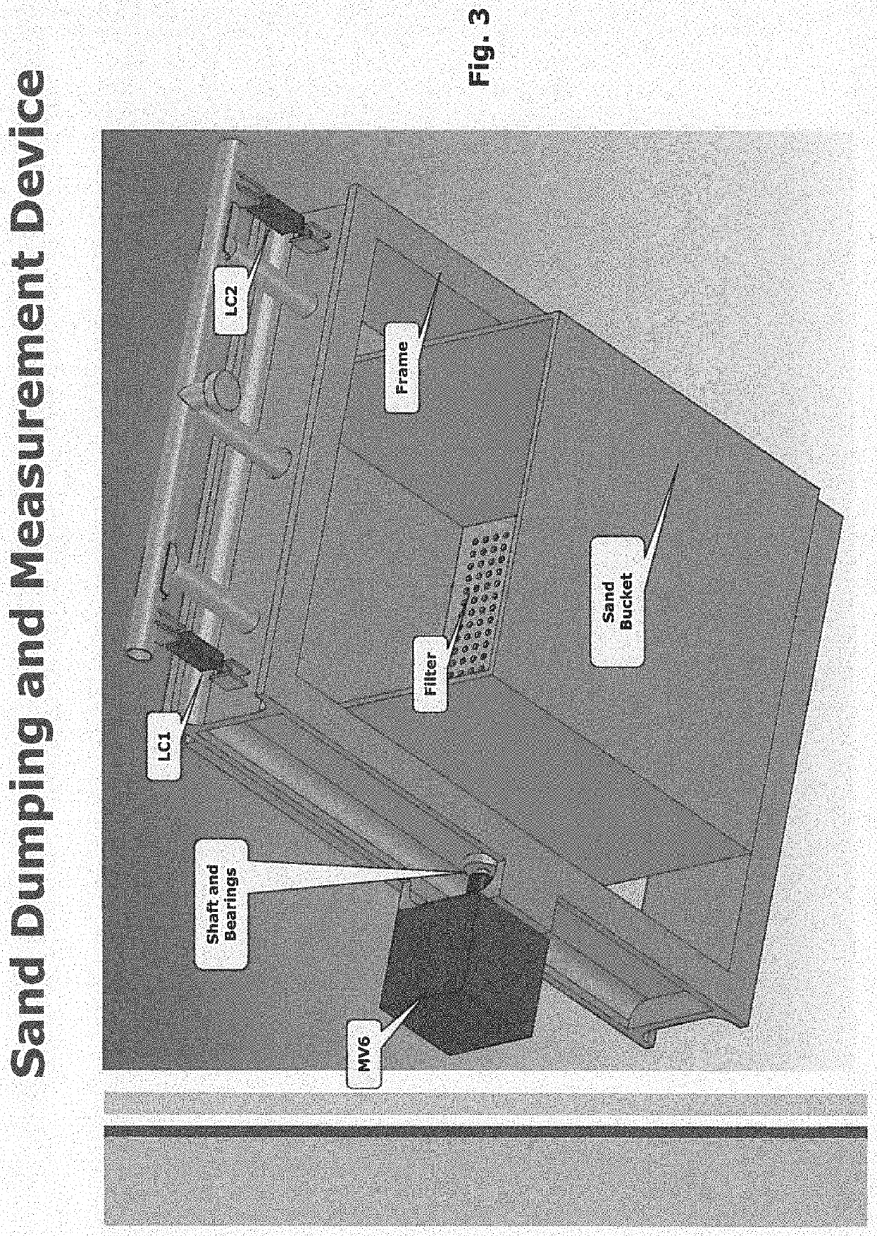
[0030]FIG. 1 shows an exemplary embodiment. FIG. 1 comprises three sand separators 1 each that may be a gravity or a centrifugal separator connected to a well with valves, pressure transmitters, and / or chokes. Typically, the sand separators are not on the skid or mobile trailer and neither is the automated dumping device which is usually above the frac tank. As shown in FIG. 1 there may be: 3—Electric actuated valves, one per vessel, MV1-MV3; 2—Electric actuated chokes in parallel located downstream of the chokes, MV4& MV5; 1—Electric actuated valves downstream of the chokes, MV6; 3—Pressure transmitters located upstream of the vessel valves, PT1-PT3; 1—Pressure transmitter located upstream of the of the 2 Electric actuated chokes in parallel, PT4; 1—Pressure transmitter located downstream of the of the 2 Electric actuated chokes in parallel, PT5; 1—level transmitter for the frac tanks; 1—Hand off Automatic Switch for the train; 1—Hand off Automatic Switch for the Sand dumping and m...


PUM

PropertyMeasurementUnit
Weightaaaaaaaaaa
Flow rateaaaaaaaaaa
Volumeaaaaaaaaaa

Abstract

A sand handling system having, for example, one to three sand separators are configured to be operatively connected to a well and an inlet of a common dumping vessel. Advantageously, the dumping vessel has a sensor to measure an amount of sand in the dumping vessel and provide a signal to a programmable controller which is arranged to dump the dumping vessel when a specified amount of sand is in the dumping vessel. The system automates the sand handling process and also measures and records data associated with a number of flowback parameters. The data can then be used in well design to improve oil and / or gas production, lessen sand production, reduce well damage and / or equipment corrosion due to, for example, sand.

Description

FIELD OF THE INVENTION[0001]The present invention relates generally to a mobile sand handling system and process for automated separation, management, and storage of particulates such as fracking sand.BACKGROUND AND SUMMARY[0002]Sand is typically produced from an oil and gas well for some time before the well enters a production phase. Typically, sand is separated from other flowback components, e.g., water and other fluids, with a sand separator. The sand may or may not be manually weighed before hauling it away from the wellsite. Unfortunately, such systems are labor intensive and inaccurate as to amount of sand flowback and other parameters. What is needed is an improved sand handling system that minimizes operating expenses and labor required and improves upon the drawbacks of prior art systems and processes.[0003]Advantageously, the present invention solves those issues and has additional advantages that may lead to improved oil and / or gas production, less sand production, redu...

Claims


Application Information

Patent Timeline
IPC IPC(8): B01D21/30E21B43/34B01D21/00
CPCB01D21/302B01D21/0024E21B43/34B01D2221/04B01D21/267B01D21/245E21B43/35B01D21/2483E21B21/065
Inventor CARLSON, KOBY BYRONKIEKE, MATTHEW ALLENWOODARD, SHAWN MARSHALLHAGAR, KENNETH PAUL
Owner CHEVROU USA INC
Why Eureka
Eureka Blog
Learn More