Interior trim panel for a vehicle and method of forming same

a technology for interior trim panels and vehicles, applied in the field of interior trim panels for vehicles, can solve the problems of significant limitations on the ability of conventional processes to provide, high cost of producing leather surface layers for these vehicle interior trim panels, and time-consuming

Inactive Publication Date: 2021-03-25
GM GLOBAL TECH OPERATIONS LLC
View PDF0 Cites 2 Cited by
  • Summary
  • Abstract
  • Description
  • Claims
  • Application Information

AI Technical Summary

Benefits of technology

[0010]In another exemplary aspect, a method of forming an interior trim panel for a vehicle includes providing a leather layer having a first thickness greater than five millimeters, clamping the leather layer in a frame to securely fix the edges of the leather layer, positioning the leather layer between a first compression molding die and a second compression molding die, and compressing the leather layer between the first compression molding die and the second compression molding die such that the leather layer stretches locally adjacent to the feature and reduces the thickness of the leather layer to a second thickness that is less than five millimeters adjacent the feature. The frame is positioned outside of the periphery of both the first and second compression molding dies, and the first compression molding die and the second compression molding dies define a complementary surface that includes a feature having a radius of less than five millimeters.

Problems solved by technology

The cost of producing these vehicle interior trim panels having a leather surface layer is expensive and time consuming.
Further, there are significant limitations on the ability of these conventional processes to provide a vehicle interior trim panel with a leather surface layer that defines a feature having a radius of less than five millimeters.

Method used


Image

  • Interior trim panel for a vehicle and method of forming same
  • Interior trim panel for a vehicle and method of forming same
  • Interior trim panel for a vehicle and method of forming same

Examples


Embodiment Construction

[0025]Reference will now be made in detail to several examples of the disclosure that are illustrated in accompanying drawings. Whenever possible, the same or similar reference numerals are used in the drawings and the description to refer to the same or like parts or steps. The drawings are in simplified form and are not to precise scale. For purposes of convenience and clarity only, directional terms such as top, bottom, left, right, up, over, above, below, beneath, rear, and front, may be used with respect to the drawings. These and similar directional terms are not to be construed to limit the scope of the disclosure in any manner.

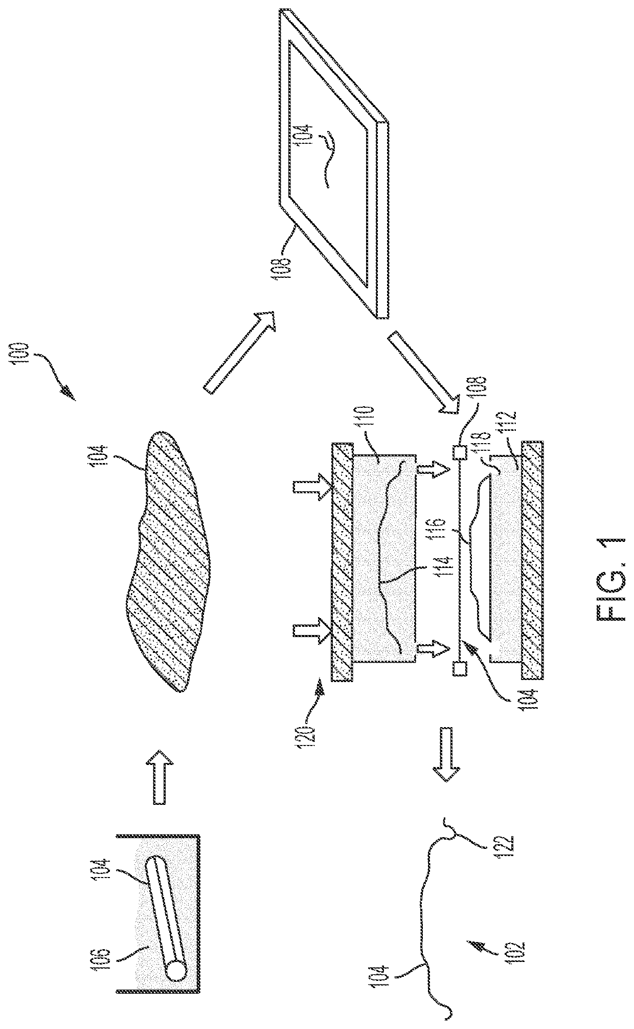
[0026]Referring now to the drawings, wherein like reference numbers correspond to like or similar components throughout the several figures, FIG. 1 is a schematic illustration of an exemplary method 100 of forming a vehicle interior trim panel 102 in accordance with the present disclosure. The exemplary method optionally starts by soaking a leather art...


PUM

PropertyMeasurementUnit
radiusaaaaaaaaaa
thicknessaaaaaaaaaa
thicknessaaaaaaaaaa

Abstract

An interior trim panel for a vehicle includes a leather layer defining a feature having a radius of less than five millimeters, and a backing layer adhered to the leather layer and providing a support structure for the leather layer. A method of forming the interior trim panel includes clamping the leather layer in a frame to securely fix the edges of the leather layer, positioning the leather layer between compression mold dies defining a complementary surface having a feature with a radius of less than five millimeters, and compressing the leather layer between the dies.

Description

FIELD[0001]The present disclosure relates to an interior trim panel for a vehicle and method for forming the interior trim panel.INTRODUCTION[0002]This introduction generally presents the context of the disclosure. Work of the presently named inventors, to the extent it is described in this introduction, as well as aspects of the description that may not otherwise qualify as prior art at the time of filing, are neither expressly nor impliedly admitted as prior art against this disclosure.[0003]Vehicle interior trim panels may form a part of a vehicle interior such as, for example, an instrument panel, a door panel, a glove box door, an armrest, a headrest, a knee bolster and the like. These vehicle interior trim panels may have a leather surface layer which may be aesthetically pleasing to vehicle occupants. Conventionally, vehicle interior trim panels having a leather surface layer are formed by applying a leather layer to an underlying supporting substrate. The supporting substrat...

Claims


Application Information

Patent Timeline
Patent Type & Authority Applications(United States)
IPC IPC(8): B29C43/18B32B3/26B32B9/02B29C43/20
CPCB29C43/184B32B3/263B32B9/025B29K2711/08B32B2307/732B32B2605/003B29C43/203B05D7/12B29C65/02B29C66/80B29L2031/58B60R13/02B29C43/02B29C43/34B29C2043/3602B32B3/02B32B9/045B32B27/28B32B27/281B32B27/285B32B27/286B32B27/288B32B27/302B32B27/304B32B27/306B32B27/308B32B27/32B32B27/34B32B27/36B32B27/365B32B27/40B32B2250/02B32B2270/00B68F1/00C14B1/26C14B1/32C14B1/56B29C43/18B29L2031/3041
Inventor RODGERS, WILLIAM R.REUTER, ROBERT JOSEPHHUANG, XIAOSONGBOUNDY, TIMOTHY M.SCHLENKE, ROBERT J.MCPECK, BRIAN
Owner GM GLOBAL TECH OPERATIONS LLC
Why Eureka
Try Eureka