Movable front panel for home appliance

Active Publication Date: 2021-04-08
BSH HOME APPLIANCES CORP +1
View PDF0 Cites 1 Cited by
  • Summary
  • Abstract
  • Description
  • Claims
  • Application Information

AI Technical Summary

Benefits of technology

The present technology provides a kick plate assembly with two pieces, a pivoting panel, and a slide-on kick plate fascia. The front panel is made of a single piece of material with side members that form perpendicular legs. The side members have slots and may have hems or a bead running along the face of the panel for strength. There could also be punch outs for attachment points for the kick plate fascia. The kick plate fascia is a box with tabs that align with the punch outs on the pivoting panel. This allows the kicker to slide down and securely attach to the pivoting panel without additional mechanical fasteners.

Problems solved by technology

These approaches make removal and / or re-attachment of the kick plate time consuming In addition, because the fasteners can be seen on the outer surface, the kick plates are visually unappealing.

Method used


Image

  • Movable front panel for home appliance
  • Movable front panel for home appliance
  • Movable front panel for home appliance

Examples


Embodiment Construction

[0035]Before the present technology is described in further detail, it is to be understood that the technology is not limited to the particular examples described herein, which may vary. It is also to be understood that the terminology used in this disclosure is for the purpose of describing only the particular examples discussed herein, and is not intended to be limiting.

[0036]The following description is provided in relation to various examples which may share one or more common characteristics and / or features. It is to be understood that one or more features of any one example may be combinable with one or more features of another example or other examples. In addition, any single feature or combination of features in any of the examples may constitute a further example.

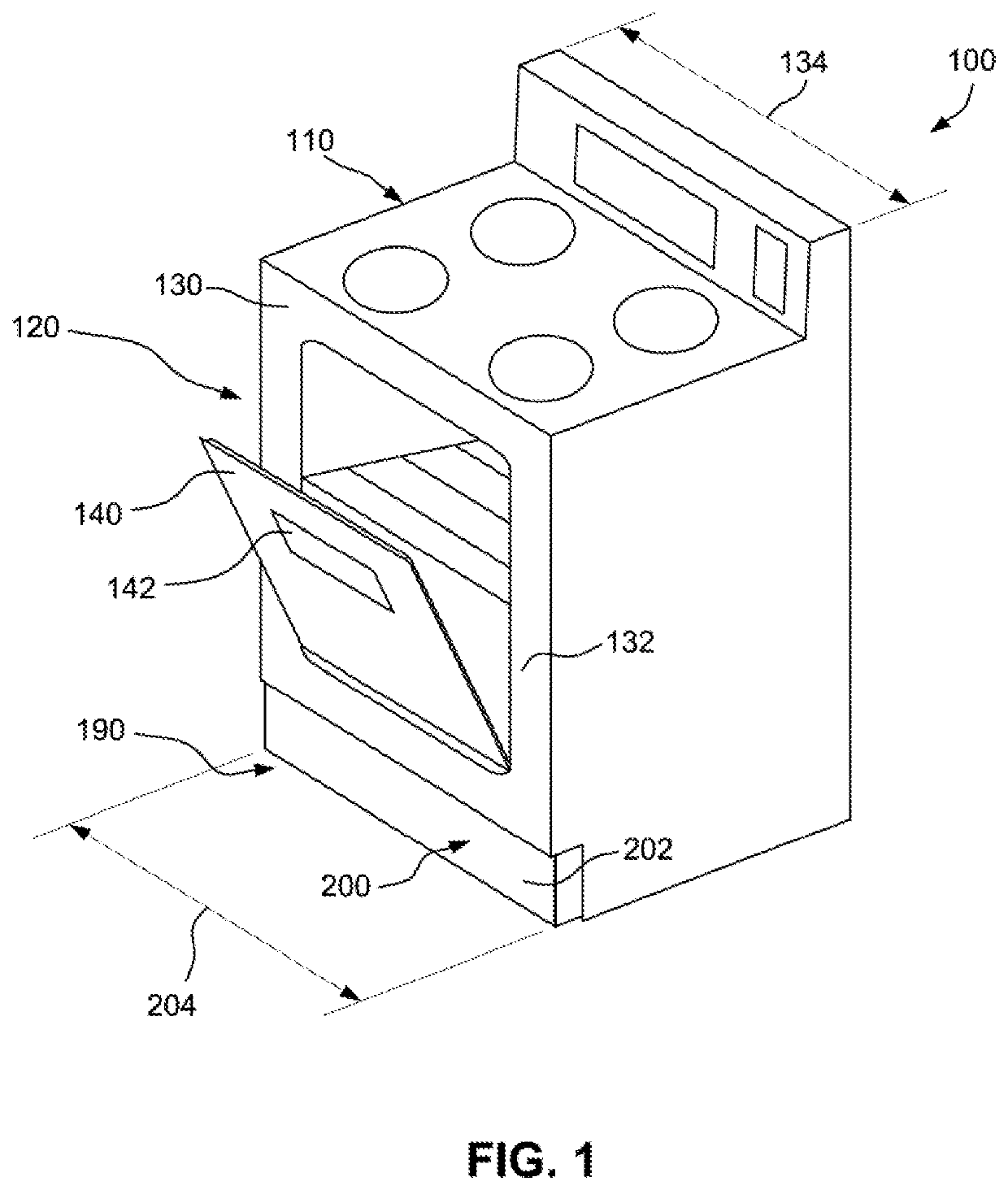
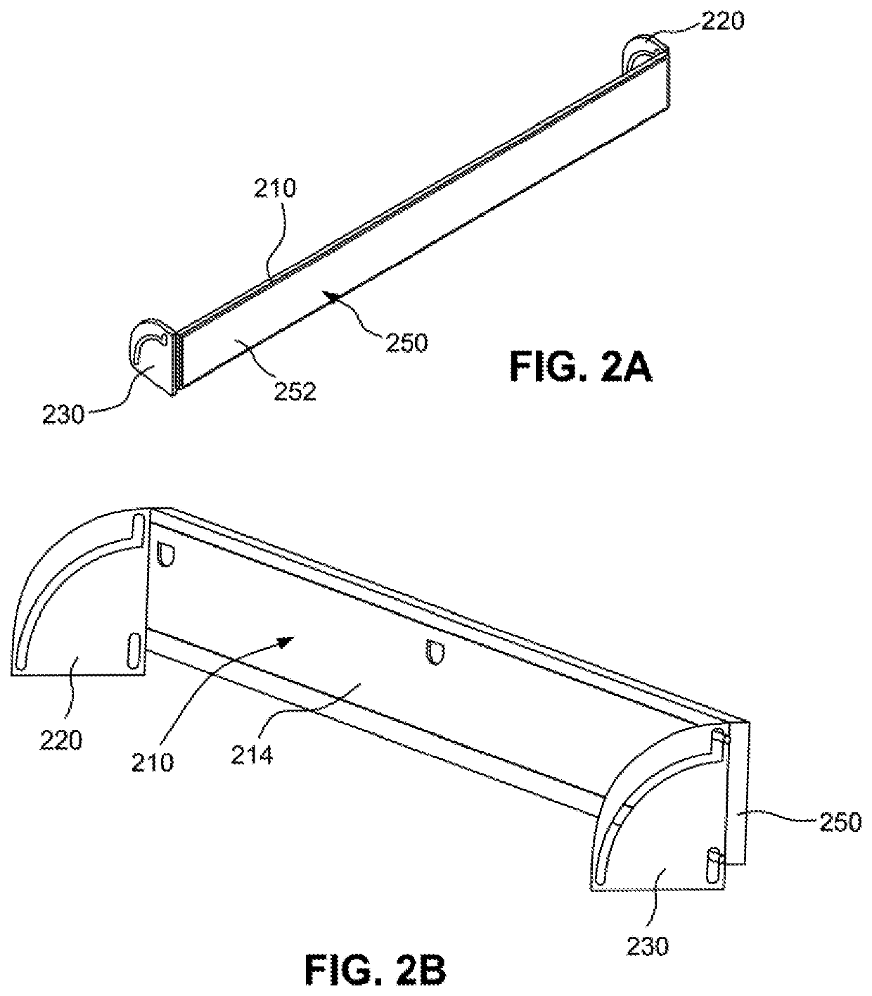
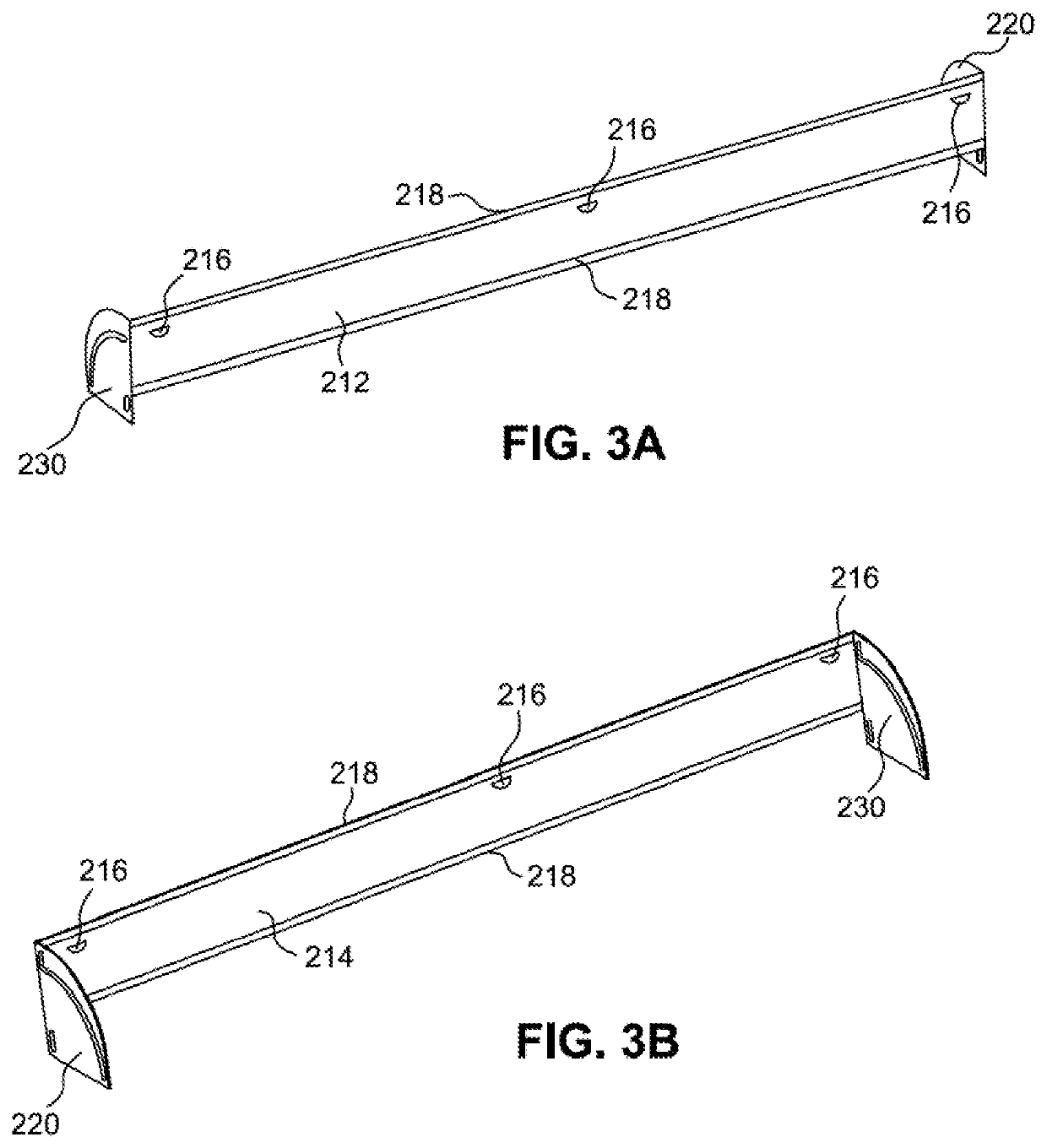
[0037]The present technology describes a kick plate assembly that may be included in a home appliance. The home appliance may be a washer, dryer, washer / dryer combination, oven, stove, refrigerator, and / or freezer...


PUM


Abstract

A domestic appliance may include: a shell; a door coupled to the shell; a treatment compartment defined at least in part by the shell and the door; a panel configured to enclose at least a portion of a cavity below the treatment compartment; an articulation arrangement coupled to the shell and configured to allow the panel to move from a closed and locked vertical position to an unlocked and open non-vertical position whilst being coupled to the shell; and a locking mechanism configured to selectively lock the panel in the vertical position. The articulation arrangement may include a first linear slot and a second slot including a linear portion and a curved portion extending from one end of the linear portion, the first linear slot engaging a first pin and the second slot engaging a second pin.

Description

FIELD OF THE TECHNOLOGY[0001]The present technology relates to home appliances, e.g., ovens, refrigerators, dishwashers, etc., with a kick plate. The present technology further relates to a movable front panel that may be used to secure the kick plate at a base of the home appliance.BACKGROUND[0002]Known home appliances, e.g., ovens, refrigerators, dishwashers, etc., have a kick plate which is secured to a base or lower-most region of the home appliance, i.e., where it can protect the home appliance against a person's shoes or debris from settling under the appliance. Further, the kick plate covers the lower-most region of the home appliance to provide a finished and complete look to the appliance while hiding appliance parts such as wiring, adjustment mechanisms, filters, pumps, etc.[0003]The attachment of the kick plate should be sufficiently secure such that it does not come loose from the appliance once the appliance is installed, e.g., during use. Conventional approaches to sec...

Claims


Application Information

Patent Timeline
IPC IPC(8): E05D11/10E05D3/18E06B7/28
CPCE05D11/1007E05D3/18A47B2096/208E05Y2900/30E06B7/28A47B2095/004E05D3/022F24C15/08
Inventor BRADEN, BENFRONCKOWIAK, JOSIAHMCIVER, IANPHILLIPS, SHAUN
Owner BSH HOME APPLIANCES CORP
Why Eureka
Try Eureka