Vehicle solar cell panel

Inactive Publication Date: 2015-07-16
TOYOTA JIDOSHA KK
View PDF7 Cites 15 Cited by
  • Summary
  • Abstract
  • Description
  • Claims
  • Application Information

AI Technical Summary

Benefits of technology

[0012]According to this aspect, the flange portion is formed by the side edge portion of the solar cell panel being bent back. Then, the solar cell panel is attached to the roof panel of the vehicle via this flange portion. Forming the flange portion by bending back the side edge portion in this way increases the sectional modulus when the solar cell panel is thought of as a beam supported at both ends in the longitudinal direction of the vehicle, for example. As a result, the rigidity and strength of the solar cell panel wi

Problems solved by technology

A solar cell can easily be mounted to a vehicle by affixing the solar cell to the surface of the roof panel using, for example, double-faced tape, an adhesive, or a magnet or the like, like the structures described in JP 10-181483 A and JP 11-240397 A. However, with this kind of structure, a solar cell is simply added

Method used


Image

  • Vehicle solar cell panel
  • Vehicle solar cell panel
  • Vehicle solar cell panel

Examples


Example

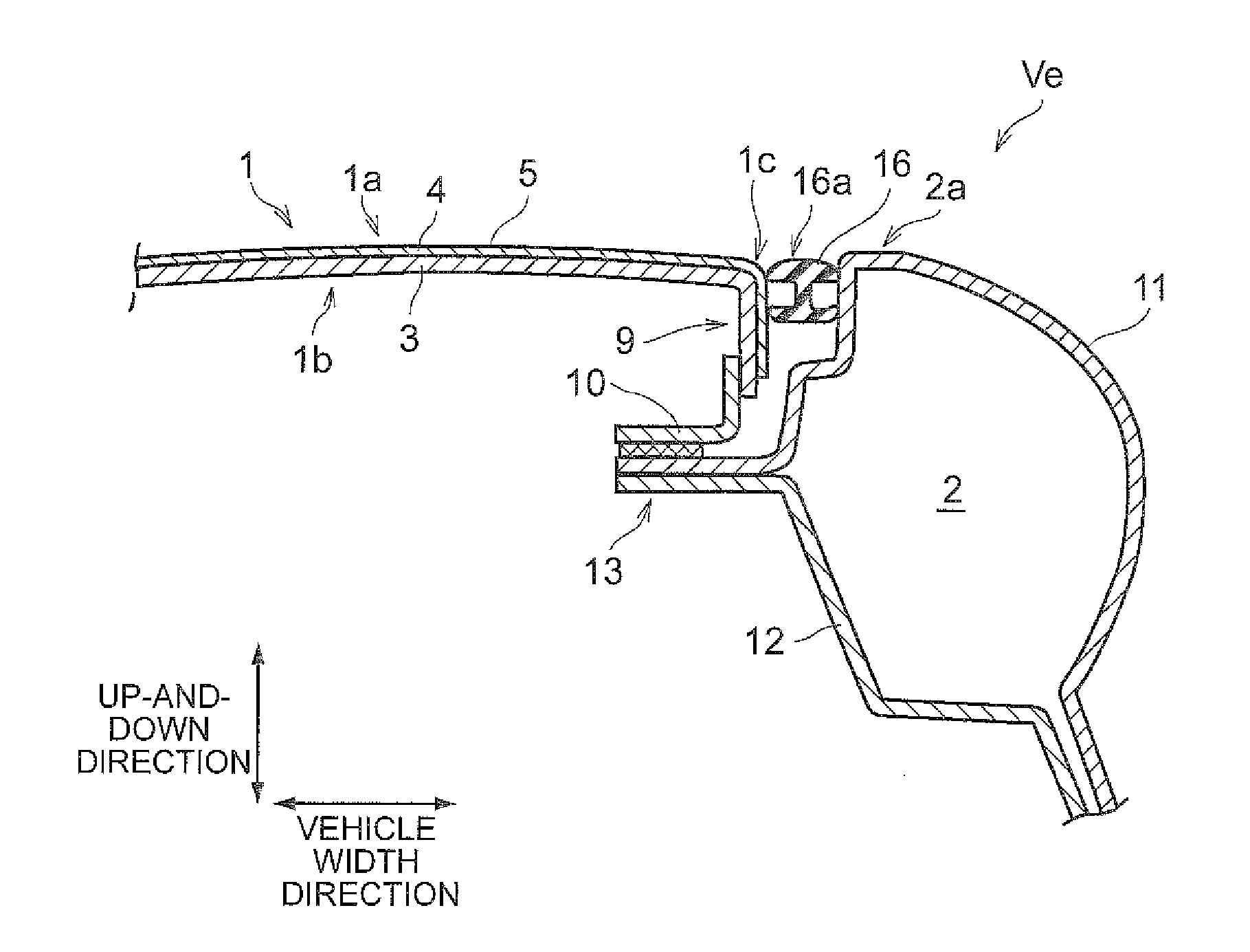
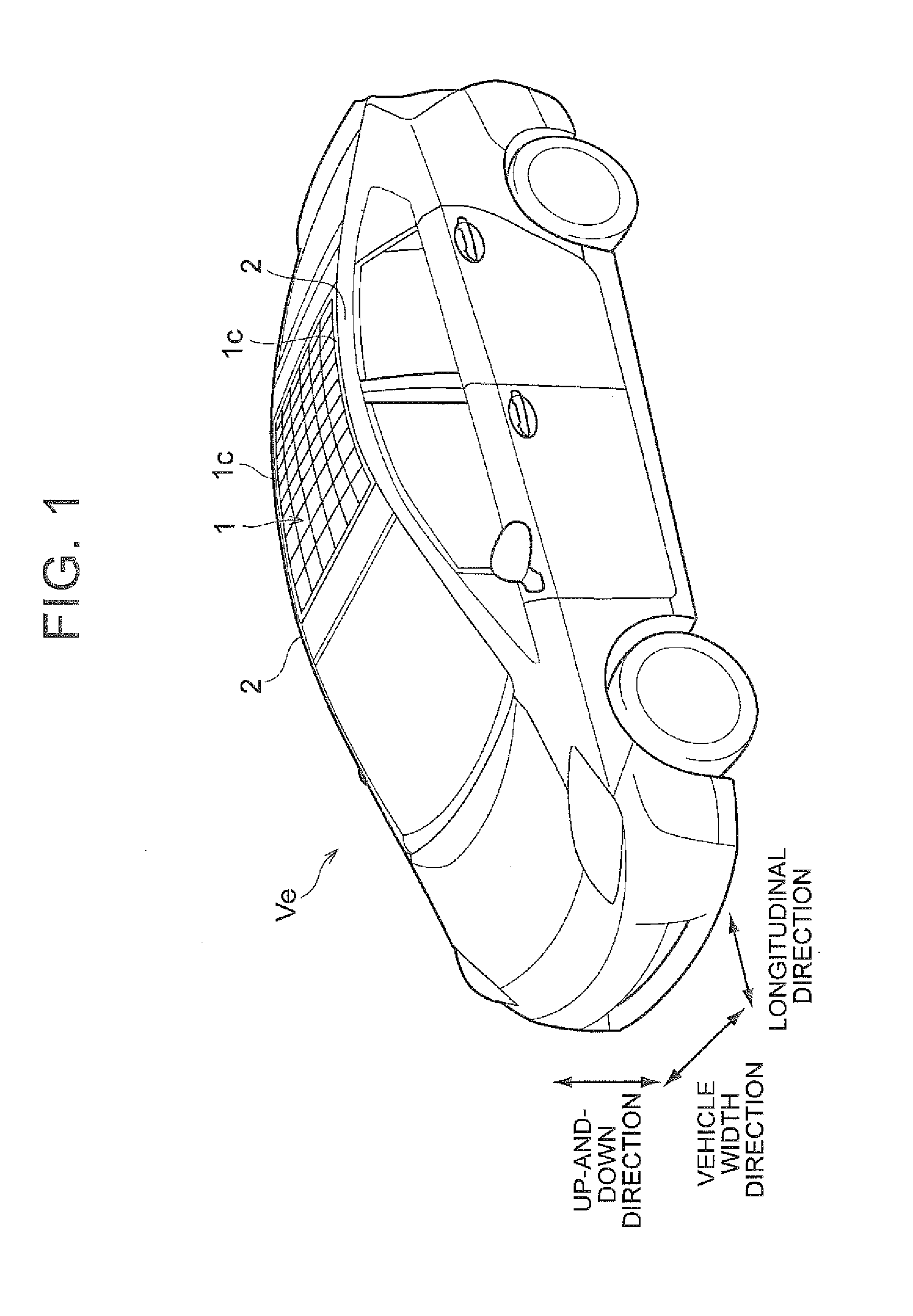
[0022]The invention will be described based on specific examples. The invention relates to the structure of a solar cell panel 1 mounted to a portion of a roof of a vehicle Ve, as shown in FIG. 1. This solar cell panel 1 is attached to roof rails 2 of the vehicle Ve, instead of an existing vehicle roof panel that is not equipped with a solar cell, as the roof panel of the vehicle Ve. That is, the solar cell panel 1 is formed in the same shape as the existing vehicle roof panel, and is configured so as to be able to be easily attached to the roof rails 2 of the vehicle Ve, in the same way in which an existing vehicle roof panel is attached to a vehicle body. In this example embodiment, portions such as the roof rails 2 that are provided in plurality may be referred to in the singular to simplify the description.

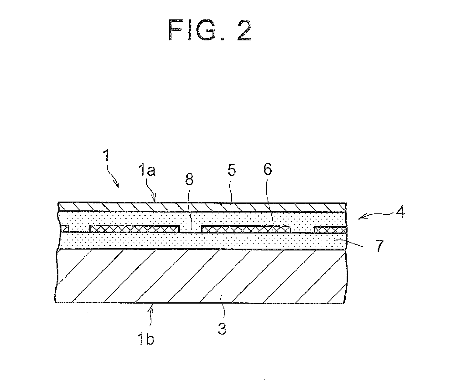
[0023]The solar cell panel 1 includes a substrate layer 3, a solar cell layer 4, and a surface protection layer 5, as shown in FIG. 2. Steel sheet, aluminum alloy sheet, or fi...


PUM


Abstract

A vehicle solar cell panel that is mounted to a vehicle provided with a roof rail includes a flange portion formed by a side edge portion of at least a portion of the vehicle solar cell panel being bent back toward a back side of a light receiving surface. A roof panel of the vehicle is formed by the flange portion being attached to the roof rail.

Description

INCORPORATION BY REFERENCE[0001]The disclosure of Japanese Patent Application No. 2014-005224 filed on Jan. 15, 2014 including the specification, drawings and abstract is incorporated herein by reference in its entirety.BACKGROUND OF THE INVENTION[0002]1. Field of the Invention[0003]The invention relates to the structure of a vehicle solar cell panel to be installed in a vehicle.[0004]2. Description of Related Art[0005]Japanese Patent Application Publication No. 10-181483 (JP 10-181483 A) describes technology related to a solar cell installed in a vehicle. The solar cell described in JP 10-181483 A is formed in a flat plate shape with solar cell elements stacked on a flexible circuit board. A rubber or resin terminal member is attached to an outer edge portion of this solar cell. Also, the solar cell is mounted to a surface of a roof panel of the vehicle with an adhesive or a magnet, while being supported by the terminal member.[0006]Also, Japanese Patent Application Publication No....

Claims


Application Information

Patent Timeline
IPC IPC(8): B60K16/00H02S30/10H02S20/30
CPCB60K16/00B60K2016/003H02S30/10H02S20/30Y02T10/90Y02E10/50
Inventor SHIRAI, YASUHIRO
Owner TOYOTA JIDOSHA KK
Why Eureka
Try Eureka