Regulating valve with integrated purge function
- Summary
- Abstract
- Description
- Claims
- Application Information
AI Technical Summary
Benefits of technology
Problems solved by technology
Method used
Image

Examples
Embodiment Construction
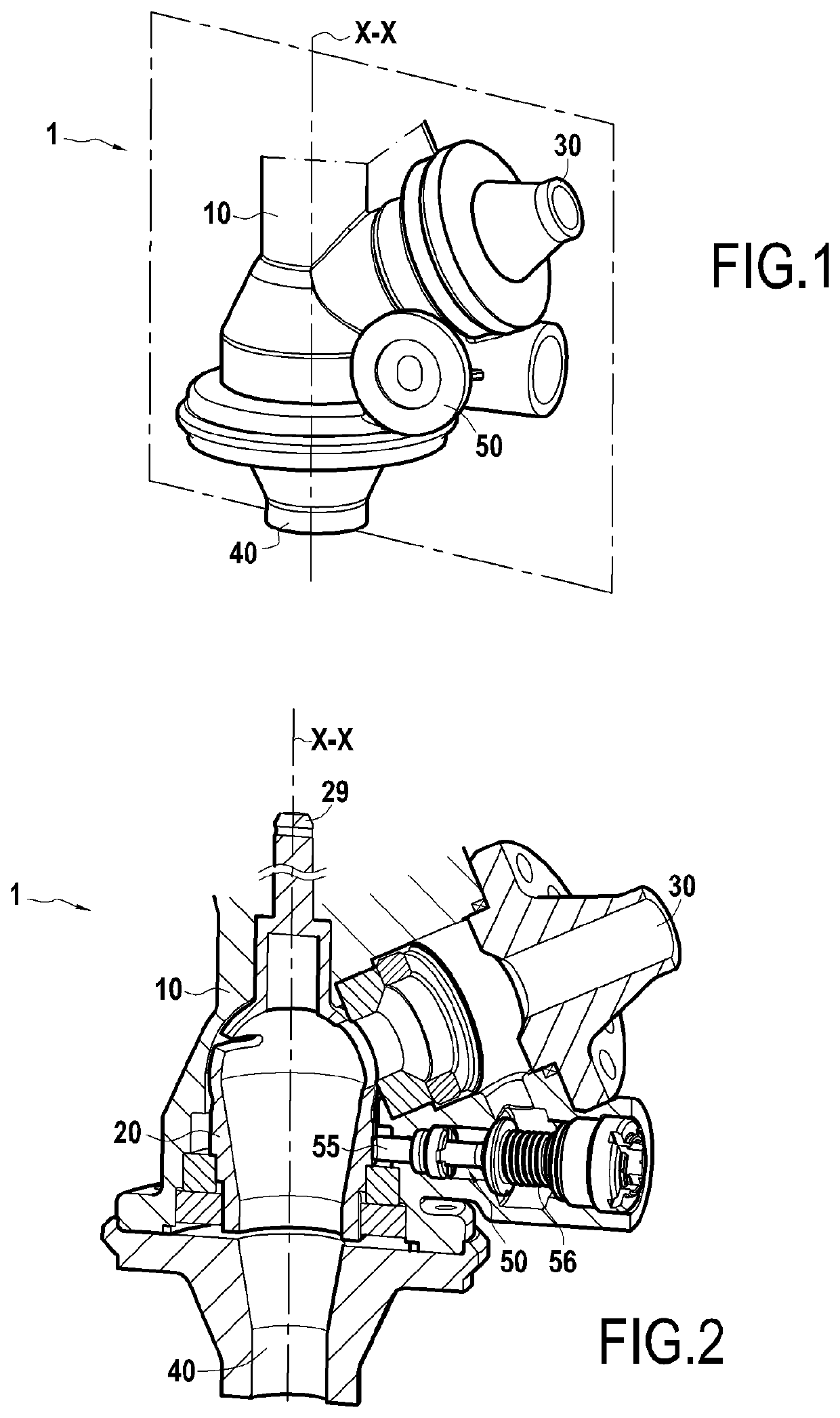
[0024]A valve is described hereinafter according to one aspect of the invention with reference to the figures.
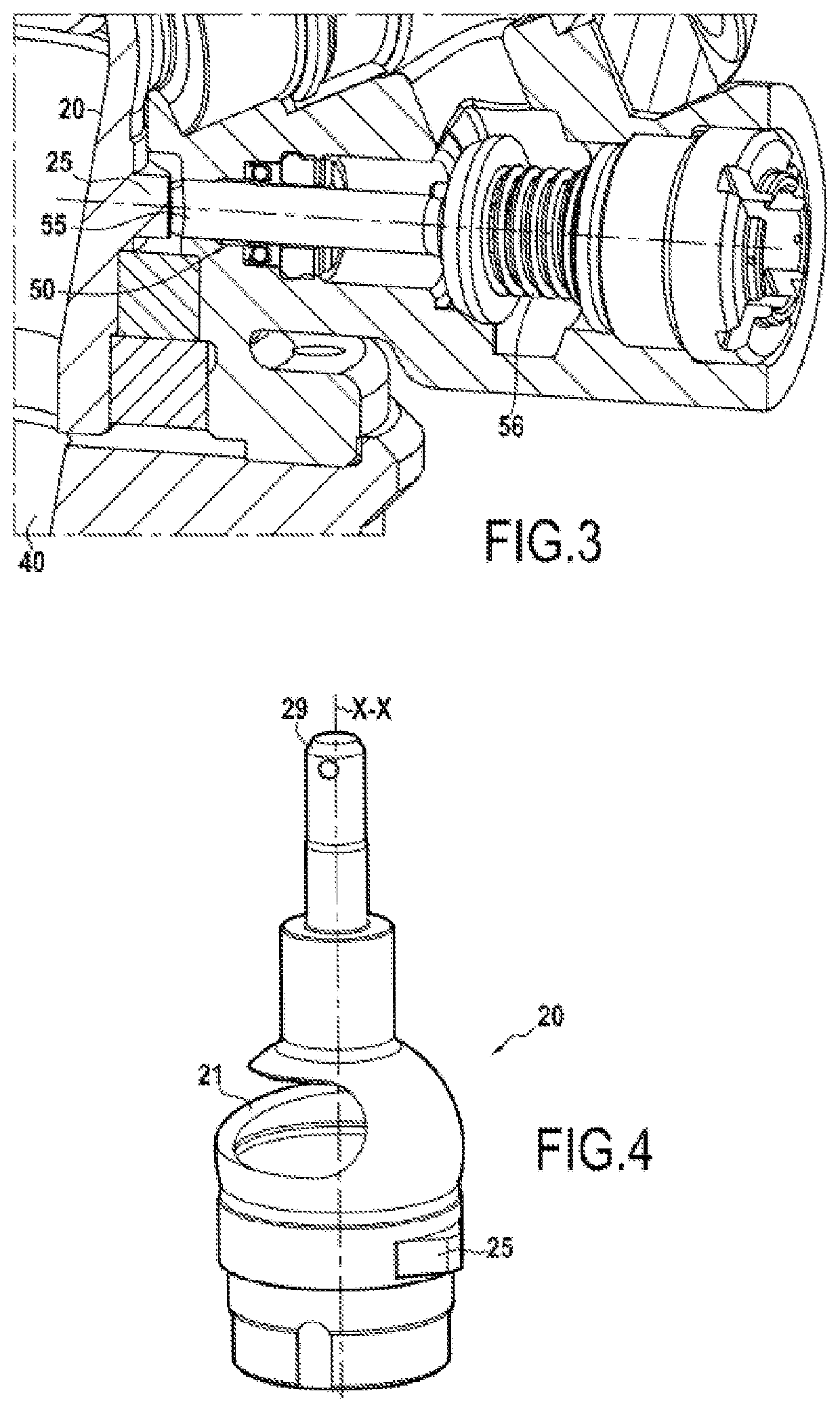
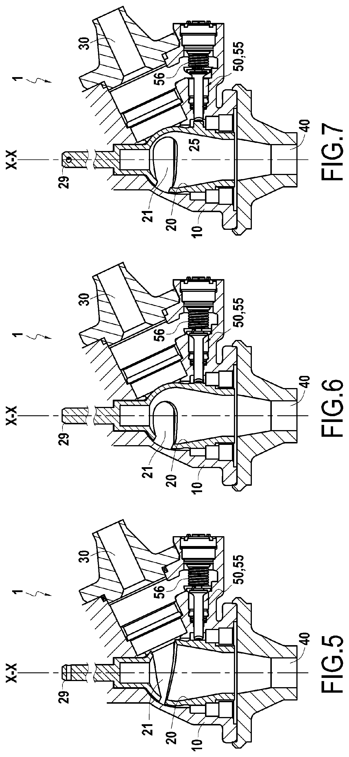
[0025]FIG. 1 represents a view of a valve according to one aspect of the invention, FIG. 2 represents a sectional view thereof, and FIG. 3 is a detailed sectional view of a specific area of the valve.
[0026]The valve 1 comprises a valve body 10 in which a plug 20 is mounted, and to which an upstream duct 30, a downstream duct 40, a purge duct 50, and a shutter 55 are connected.
[0027]The designations “upstream duct” and “downstream duct” are used depending on the operation envisaged for the valve 1. The upstream duct 30 is intended to be connected to a fluid supply source (for example a cryogenic propellant) such as a tank or a turbopump, and the downstream duct 40 is intended to be connected to a propulsion member of a spacecraft, such as a gas generator.
[0028]The upstream duct 30 and the downstream duct 40 are thus fluidly connected to an internal volume of the valve body 10...
PUM
 Abstract
Description
Claims
Application Information
 - R&D Engineer
- R&D Manager
- IP Professional
- Industry Leading Data Capabilities
- Powerful AI technology
- Patent DNA Extraction
Browse by: Latest US Patents, China's latest patents, Technical Efficacy Thesaurus, Application Domain, Technology Topic.
© 2024 PatSnap. All rights reserved.Legal|Privacy policy|Modern Slavery Act Transparency Statement|Sitemap