

Ceramic applied electronic device and connector
- Summary
- Abstract
- Description
- Claims
- Application Information
AI Technical Summary
Benefits of technology
Problems solved by technology
Method used
Image

Examples
first embodiment
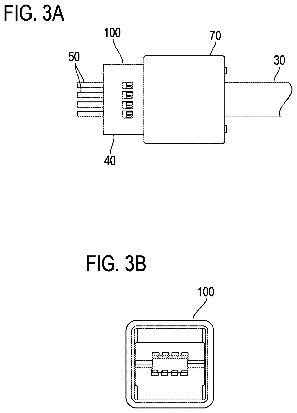
[0138]FIGS. 3A, 3B, 3C, 3D, 4A, and 4B illustrate a configuration of a connector according to a first embodiment. A connector 100 is used to connect a ceramic element incorporated in a ceramic applied electronic device and lead wires for connection with an external apparatus. FIGS. 3A, 3B, 3C, 3D, 4A, and 4B illustrate the connector 100, to which a ceramic element 30 is connected.
[0139]The connector 100 includes two insulators 40, eight contacts 50, two spring components 60, and a cylindrical sleeve 70 which is hollow and rectangular in sectional shape. FIG. 5 is a partial exploded view of the connector 100, and FIGS. 6A and 6B illustrate details of the insulator 40. FIGS. 7A, 7B, and 8 illustrate the connector 100, to which the ceramic element 30 is not connected.
[0140]The two insulators 40 each hold four contacts 50 aligned at a lower surface 40a. The two insulators 40 are arranged such that the lower surface 40a of one of the two insulators 40 and the lower surface 40a of the oth...
second embodiment
[0168]A configuration of a connector according to a second embodiment for connection of terminal electrodes of a ceramic element and lead wires will be described.
[0169]FIGS. 11A and 11B illustrate a connector 200, to which a ceramic element 30 is connected. FIG. 12 is a partial exploded view of the connector 200. FIGS. 13A and 13B illustrate details of an insulator 40′. FIGS. 14A and 14B illustrate the connector 200, to which the ceramic element 30 is not connected. Same constituent elements as those of the connector 100 are denoted by same reference characters, and a detailed description thereof will be omitted.
[0170]The connector 200 is the same as the connector 100 except for shapes of two spring components 60′ and shapes of two insulators 40′.
[0171]The spring component 60′ has a square flat plate portion 61, two turnback pieces 64, and two mounting pieces 65, as illustrated in FIGS. 12, 14A, and 14B. The two turnback pieces 64 are continuous with two ends of the flat plate porti...
third embodiment
[0178]A configuration of a connector according to a third embodiment for connection of terminal electrodes of a ceramic element and lead wires will be described.
[0179]FIGS. 15A, 15B, 15C, 15D, 16A, and 16B illustrate a connector 300 according to the third embodiment, to which a ceramic element 30 is connected. FIG. 17 is a partial exploded view of the connector 300. FIGS. 18A and 18B illustrate details of an insulator 40″. FIGS. 19A and 19B illustrate the connector 300, to which the ceramic element 30 is not connected. Same constituent elements as those of the connector 100 are denoted by same reference characters, and a detailed description thereof will be omitted.
[0180]The spring component 60″ has a square flat plate portion 61 and two turnback pieces 67, as illustrated in FIGS. 17, 19A, and 19B. The two turnback pieces 67 are continuous with two ends of the flat plate portion 61 in a direction perpendicular to a traveling direction of a sleeve 70′ which travels toward the spring ...
PUM
 Abstract
Description
Claims
Application Information