
Photocathode, electron tube, and method of assembling photocathode

a technology of electron tube and photocathode, which is applied in the field of photocathode, electron tube, and method of assembling photocathode, can solve the problems of certain decrease in workability, and achieve the effect of simplifying notably, improving the efficiency of the assembly work of the photocathode, and simplifying notably

Active Publication Date: 2006-02-21
HAMAMATSU PHOTONICS KK
View PDF9 Cites 4 Cited by
  • Summary
  • Abstract
  • Description
  • Claims
  • Application Information

AI Technical Summary

Benefits of technology

The present invention provides a photocathode, an electron tube, and a method of assembling a photocathode that solves the problems of conventional electron tubes. The technical effects of the invention include improved workability, reliability, and stability. The invention provides a holding member with a fixing structure that presses the photocathode plate against the light transparent member, ensuring good contact and retention. The holding member has a first opening portion in which the photocathode plate is disposed. A supporting plate is sandwiched between the light transparent member and the holding member, with a second opening portion exposing a part of the photocathode plate. The invention also provides a method of assembling a photocathode that simplifies the work of positioning the photocathode plate and improves assembly efficiency. Additionally, the invention provides a photocathode with a bias voltage applied between both sides of the photocathode plate, eliminating the necessity of access using a wire, a pin, or the like to a minus terminal of a power supply for applying a bias voltage.

Problems solved by technology

As a result, they have found problems as follows.
This causes a certain decrease in workability.

Method used


Image

  • Photocathode, electron tube, and method of assembling photocathode
  • Photocathode, electron tube, and method of assembling photocathode
  • Photocathode, electron tube, and method of assembling photocathode

Examples


Embodiment Construction

[0032]Preferred embodiments of a photocathode, a method for assembling a photocathode, and an electron tube according to the present invention are described below in detail with reference to the drawings.

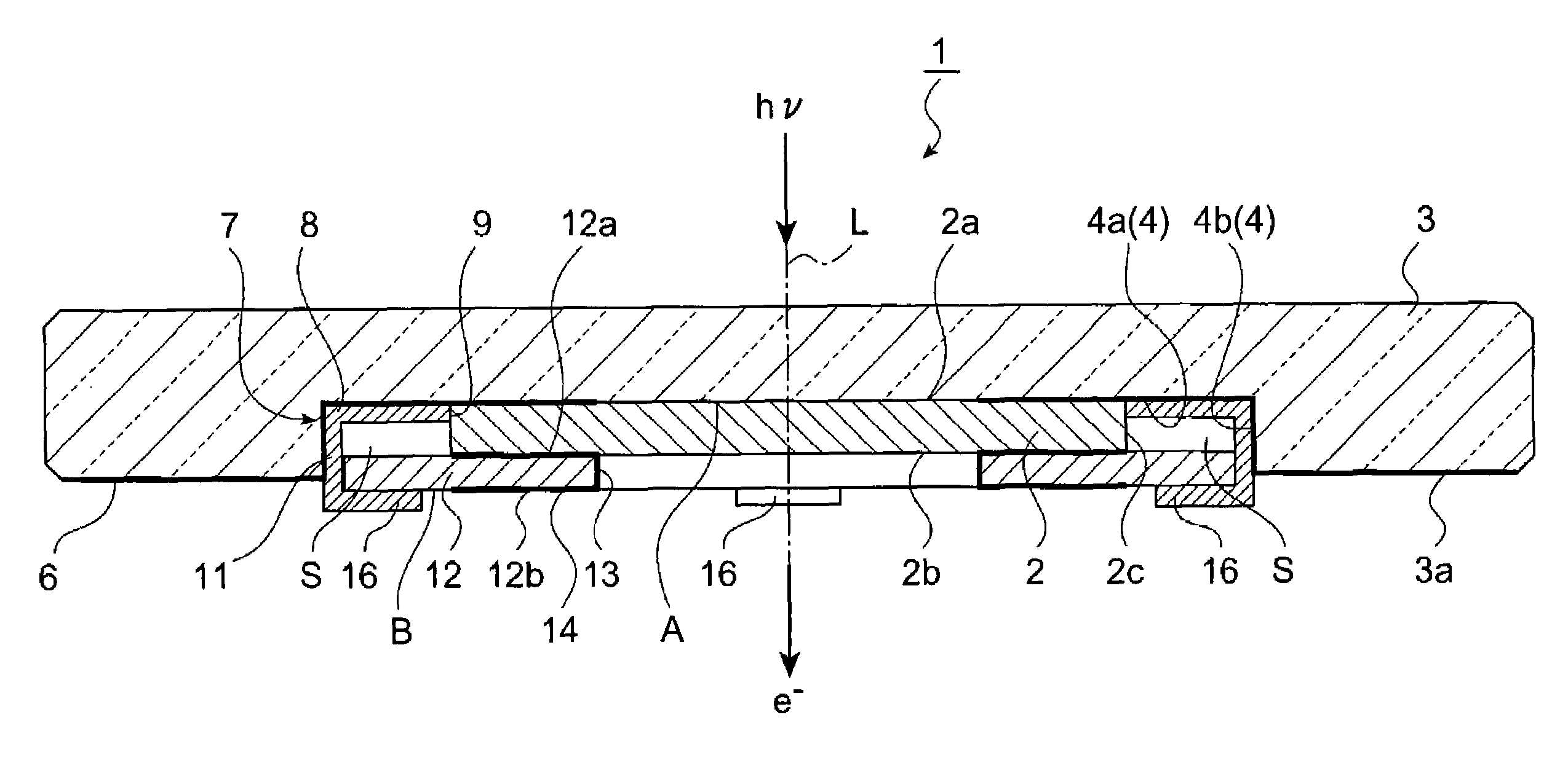
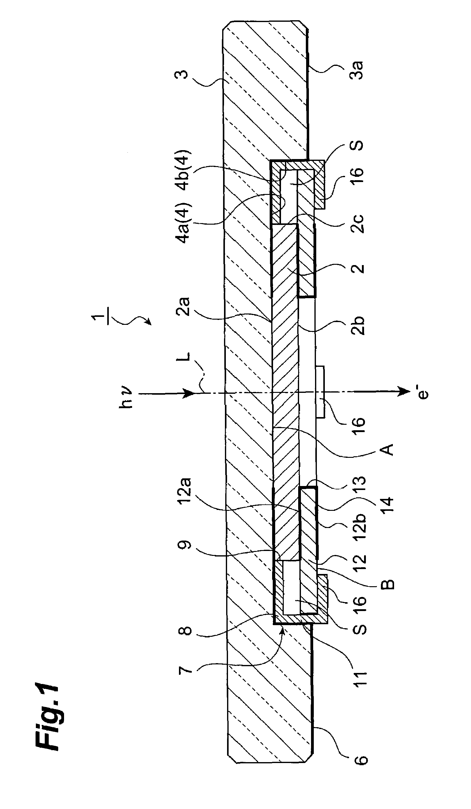
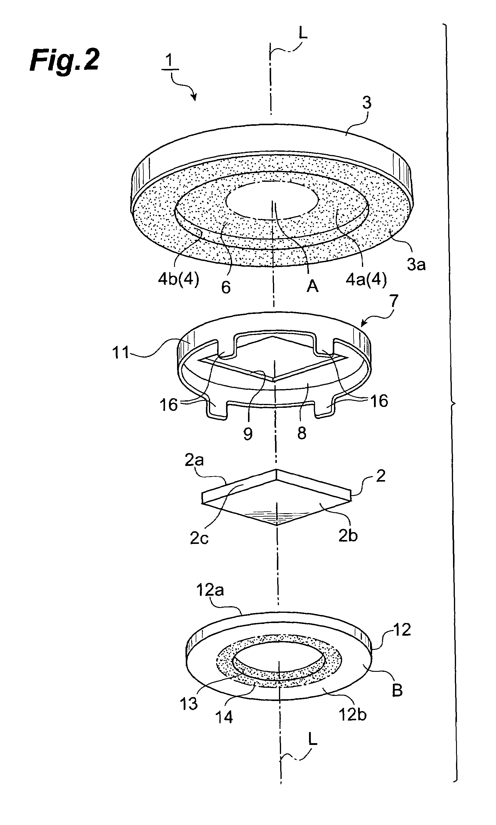
[0033]FIG. 1 is a cross sectional view showing an embodiment of a photocathode according to the invention, FIG. 2 is an exploded perspective view showing the photocathode of FIG. 1, and FIG. 3 is a bottom view showing the photocathode of FIG. 1. The photocathode 1 shown in FIG. 1 is a transmission type field assist photocathode comprising a photocathode plate (a semiconductor crystal functioning as a so-called photoelectric surface) 2 for emitting photoelectrons (e−) toward the rear direction (downward) in response to light (hν) incident from the front direction (from above). This photocathode 1 is used as a photoelectric conversion portion in an electron tube such as a photomultiplier. The photocathode 1 comprises a disk-shaped light transparent plate (light transparent member) 3 f...


PUM


Abstract

The invention relates to a photocathode and the like having such structure for holding a photocathode plate on a light transparent member with good reliability and workability. In the photocathode, claw portions of a holding member fixed to the light transparent member is pressed against the lower surface of a supporting plate so that a photocathode plate is sandwiched between the light transparent member and the supporting plate. Thus, the supporting plate is pressed against the photocathode plate, so that the photocathode plate is pressed against the light transparent plate by the supporting plate. This allows the photocathode plate to be held reliably by the light transparent member. This simple configuration further provides good workability in assembling.

Description

BACKGROUND OF THE INVENTION[0001]1. Field of the Invention[0002]The present invention relates to a photocathode in which light transmitted through a light transparent member is incident on a photocathode plate so that photoelectrons are emitted, an electron tube including the photocathode, and a method of assembling the photocathode.[0003]2. Related Background Art[0004]Such techniques according to the prior art include an electron tube disclosed in Japanese Patent Laid-Open No. 2002-42636 (Reference 1). In the electron tube disclosed in Reference 1, a photocathode plate is sandwiched between a faceplate and a supporting plate, and a pin embedded in the faceplate is joined with the supporting plate, so that the photocathode plate is fixed to the faceplate. In a case where this electron tube is used as a field assist type photocathode for detecting light with a long wavelength, when the pin and the supporting plate are formed of conductive materials, a bias voltage can be applied to t...

Claims


Application Information

Patent Timeline
Patent Type & Authority Patents(United States)
IPC IPC(8): H01J40/14H01J9/12H01J40/06H01J43/08
CPCH01J43/28H01J43/08
Inventor NEGI, YASUHARUEGAWA, YASUYUKIHIROHATA, TORUNIIGAKI, MINORU
Owner HAMAMATSU PHOTONICS KK
Learn More