
APPARATUS AND METHOD FOR QoS AWARE GTP-U TRANSPORT IN MOBILE NETWORKS

Active Publication Date: 2021-05-27
NETSIA INC
View PDF2 Cites 7 Cited by
  • Summary
  • Abstract
  • Description
  • Claims
  • Application Information

AI Technical Summary

Benefits of technology

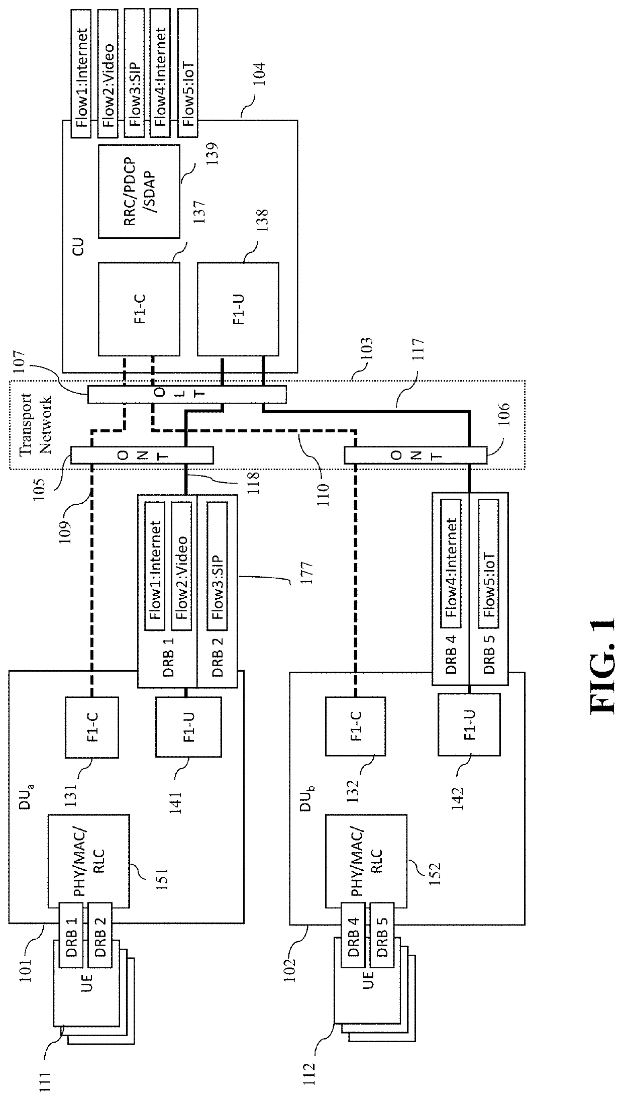
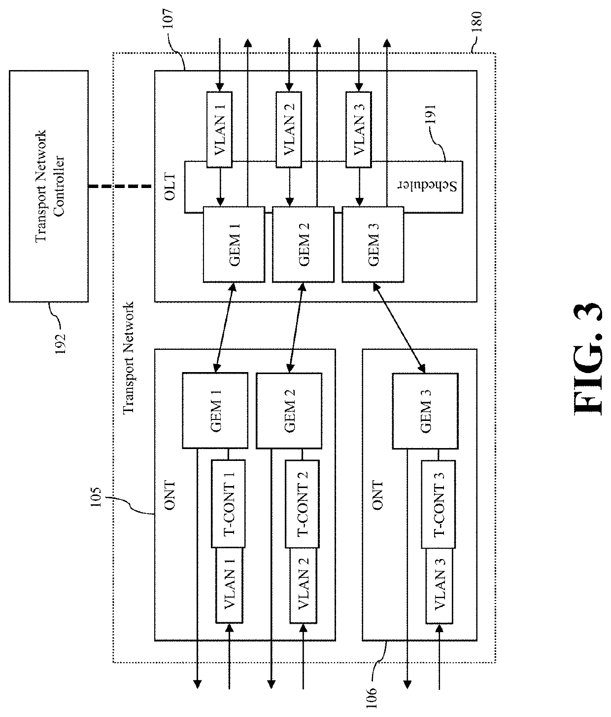
This patent proposes a solution for the fronthaul transport network in 5G, which is a network that connects the central unit and multiple distributed units. The solution involves using a passive optical network (PON) with optical network terminals (ONTs) and an optical line terminal (OLT). An intelligent transport controller controls the ONTs and OLT. The patent proposes that the upper-layer quality of service requirements for different data radio bearers (DRBs) are mapped onto the lower-layer quality of service capabilities of the transport network. This ensures that differentiated DRBs are placed on equal quality of service components of the transport network. The proposal also introduces a new control interface between the transport network controller and the CU / DU. The technical effect of this patent text is to ensure better connectivity and efficient data transmission in 5G network.

Problems solved by technology

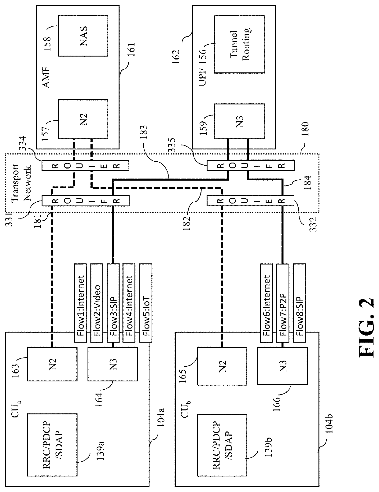
Exactly the same problem exists for the N3 interface that is carried on another type of backhaul transport network as well.

Method used


Image

  • APPARATUS AND METHOD FOR QoS AWARE GTP-U TRANSPORT IN MOBILE NETWORKS
  • APPARATUS AND METHOD FOR QoS AWARE GTP-U TRANSPORT IN MOBILE NETWORKS
  • APPARATUS AND METHOD FOR QoS AWARE GTP-U TRANSPORT IN MOBILE NETWORKS

Examples


first embodiment

[0052]FIG. 4 illustrates this invention. In this embodiment, transport network controller 192 has TN-C interface 231a towards DU and TN-C interface 231b towards the CU. DU has a new function called QoS mapping 202a and CU has the reciprocal function 202b. DU has a new database called QoS mapping DB 207a and CU has the reciprocal function 207b. A trivial mapping of this configuration is also applicable between the CU and UPF, wherein both CU and UPF have TN-C interfaces towards the transport network controller. Hence, it will not be recited here.

[0053]Although a single transport network controller is illustrated in FIG. 4 for simplicity, there may be multiple transport network controllers, (particularly, when each transport network controller is being associated with a specific slice) and therefore multiple TN-C interfaces at each end. The mapping between slice and TN-C interface is stored in DU, CU and UPF.

[0054]The basic TN-C interface messages are illustrated in FIG. 5 and compris...

second embodiment

[0074]An exemplary message flow corresponding the second embodiment is shown in FIG. 8. The process starts before a UE context setup procedure between the DU and CU using the F1-C interface. F1-C creates UL TEID and sends it with the associated QoS profile identified by NSSAI, flow 5QIs and DRB 5QI to QoS Mapping function. QoS Mapping first tests the achievability of new QoS requirements with existing ones through available VLANs of the transport network. If the new QoS requirements are not achievable with the QoS properties of the existing VLANs, QoS Mapping function sends a Transport Network QoS Request to transport network controller to add a new transport network capability (such as a new VLAN tag, GEM port, TCONT, etc.) corresponding to the requested QoS profile. Depending on success or failure in Transport Network QoS Response, the QoS Mapping generates the layer 2-4 properties for both uplink and downlink QoS profiles of the DRB. QoS Mapping function first sends UL layer 2-4 ...


PUM


Abstract

The embodiments in this invention extend distributed unit (DU), central unit (CU) and control plane of F1 (F1-C) capabilities so that differentiated DRBs of F1-U are placed on differentiated transport network components of equivalent QoS. This is achieved by a transport-aware DU and CU that can map each F1-U DRB into appropriate OSI layer 2-4 headers and can, subsequently, store such mappings. The F1-C interface is extended to distribute the layer 2-4 headers acquired from the transport network controller to the DUs and CU. A new control interface TN-C is defined between transport network controller and CU / DU. Furthermore, a trivial mapping of those embodiments is applicable for the N3 interface as well, which solves the same problem on the backhaul transport network.

Description

BACKGROUND OF THE INVENTIONField of Invention[0001]The present invention relates to a system and method for a 5th generation (and beyond) cellular network's fronthaul and backhaul components comprising a radio access network (RAN) and a transport network such as passive optical network (PON) or SDN.Discussion of Related Art[0002]Any discussion of the prior art throughout the specification should in no way be considered as an admission that such prior art is widely known or forms part of common general knowledge in the field.[0003]The high bitrate and coverage requirements of 5G have been achieved by decomposing the Radio Access Network (RAN) into denser deployment of Distributed Units (DUs) wherein these small units are deployed anywhere with potentially high traffic requirements and managed by a Central Unit (CU). In effect, a CU and a collection of its subtending DUs form a logical base station, gNodeB or gNB. This decomposition created the necessity for defining yet another inter...

Claims


Application Information

Patent Timeline
IPC IPC(8): H04W48/18H04W48/06H04W28/02H04W76/12H04W76/11H04L12/46
CPCH04W48/18H04W48/06H04W28/0268H04L12/4633H04W76/11H04L12/4641H04W76/12H04W28/0263H04W28/24H04L12/4645H04L47/2491H04W88/085
Inventor AKMAN, ARDAALTAY, CANYIGIT, BEYTULLAHGORKEMLI, BURAKYARGICOGLU, BURCUOKTAY, OGUZCIVANLAR, SEYHAN
Owner NETSIA INC
Learn More