
Display device

a display device and display technology, applied in the field of display devices, can solve the problems of difficulty for users to know the state of the display device, and achieve the effects of minimizing user inconvenience, minimizing the case, and minimizing the inconvenience of users

Active Publication Date: 2021-06-03
LG ELECTRONICS INC
View PDF0 Cites 0 Cited by
  • Summary
  • Abstract
  • Description
  • Claims
  • Application Information

AI Technical Summary

Benefits of technology

The present invention provides a display device with improved accuracy of user recognition. The display device informs the user of the state of the device without the user's separate request, which minimizes user inconvenience. The device can detect the presence of the user through whether or not connected to the same AP and minimize the case where the alarm is unnecessary output. The device limits the maximum number of alarm outputs and provides various information required for the user. This minimizes unnecessary power consumption when there is no user and improves the user experience.

Problems solved by technology

However, when the entire display area of the display device is drawn in the housing, it may be difficult for the user to know what state the display device is in.

Method used


Image

  • Display device
  • Display device
  • Display device

Examples


first embodiment

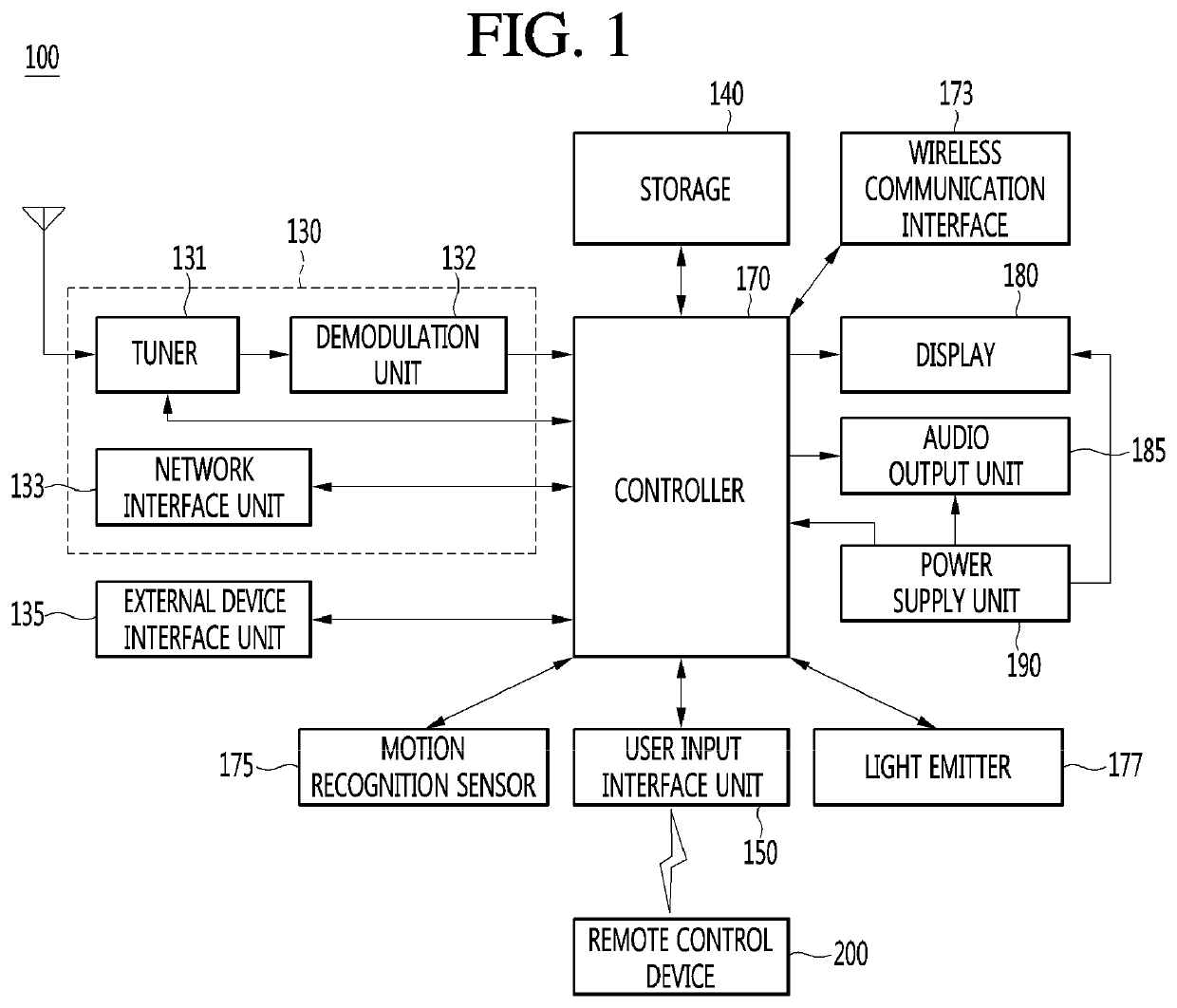
[0064]The motion recognition sensor 175 can detect a user's motion. The motion recognition sensor 175 can detect a motion generated near the display device 100. the motion recognition sensor 175 can be configured as a radar. Also, the radar can detect a motion by radiating electromagnetic waves and subsequently receiving reflected electromagnetic waves. The radar can detect whether a motion is generated near the display device 100.

second embodiment

[0065] the motion recognition sensor 175 can be configured as a camera. The camera can capture an image near the display device 100 and the controller 170 can detect a motion by analyzing the captured image.

[0066]Further, the embodiments described above are merely examples for convenience of description, and the motion recognition sensor 175 can detect a motion in various ways through various components. In addition, the first and second embodiments described above can be implemented separately or in combination.

[0067]In addition, the light emitter 177 can emit predetermined light to the outside. For example, the light emitter 177 can be an LED bar including at least one LED. The display 180 can convert image signals, data signals, or OSD signals, which are processed in the controller 170, or images signals or data signals, which are received in the external device interface unit 135, into R, G, and B signals to generate driving signals.

[0068]The display 180 can include a rollable d...

third embodiment

[0137] the display device 100 has a limited maximum number of times to output the alarm for a preset time, and thus, the controller 170 can output the alarm less than the maximum number of times for the preset time, regardless of the alarm output condition.

[0138]Next, FIG. 14 is a flowchart illustrating a method of outputting an alarm at a maximum number of times or less according to an embodiment of the present disclosure. As shown, the controller 170 can set the maximum number of alarm outputs (S41). For example, the controller 170 can set the maximum number of times in advance or set the maximum number of times according to a default value (e.g., 2). Alternatively, the controller 170 can set the maximum number of times according to a user input. In this instance, the user can advantageously set a preferred number as the maximum number as necessary.

[0139]In addition, the controller 170 can count the number of times to output the alarm (S42). For example, the controller 170 can cou...


PUM


Abstract

A display device including a housing; a rollable display included in the housing; a wireless communication unit connected to an access point (AP); a motion recognition sensor configured to detect a user's motion; and a controller configured to determine if an external device is connected to the AP to which the wireless communication unit is connected, and output an alarm in response to the detection of the user's motion and the determination the external device is connected to the AP.

Description

CROSS-REFERENCE TO RELATED APPLICATIONS[0001]Pursuant to 35 U.S.C. § 119(a), this application claims the benefit of an earlier filing date and priority to Korean Application No. 10-2019-0159268 filed in the Republic of Korea on Dec. 3, 2019, the contents of which are incorporated by reference herein in its entirety.BACKGROUND OF THE INVENTIONField of the Invention[0002]The present disclosure relates to a display device, and more particularly, to a display device including a flexible display.Discussion of the Related Art[0003]A display device has a function of receiving, processing, and displaying an image to be watched by a user. For example, the display device receives a broadcast signal selected by a user among broadcast signals transmitted from a broadcasting station, separates an image signal from the received signal, and re-displays the separated image signal on a display.[0004]Recently, by virtue of development of broadcasting technology and network technology, a function of a...

Claims


Application Information

Patent Timeline
Patent Type & Authority Applications(United States)
IPC IPC(8): G08B21/18G09G5/00H04W4/02H04W76/30G08B3/10G08B7/06G08B5/36
CPCG08B21/182G09G5/006H04W4/023G08B5/36G09G2330/027G08B3/10G08B7/06H04W76/30H04N21/4126H04N21/42221H04N21/4668H04N21/44218H04N21/4882H04N21/4222H04N21/8126H04N21/43615H04N21/43637G09F9/301
Inventor JEONG, HYO JEONGJANG, YOON SUK
Owner LG ELECTRONICS INC
Learn More