Supercharge Your Innovation With Domain-Expert AI Agents!

Non-destructive testing couplant providing apparatus and method

a technology of couplant and testing apparatus, applied in the field of non-destructive testing, can solve the problems of high cost, large quantity of fluid, fluid/water also presents a contamination problem, etc., and achieve the effect of facilitating fluid as a couplan

Active Publication Date: 2021-06-10
MAGGIO SAM
View PDF4 Cites 2 Cited by
  • Summary
  • Abstract
  • Description
  • Claims
  • Application Information

AI Technical Summary

Benefits of technology

In this patent, there is described a device with a container for moving fluid without it leaking out. This makes use of a flexible membrane which helps keep the fluid inside while still allowing sensors or probes to be used on them. Using less fluid means fewer chances of collecting unwanted substances during non-destructive testing (NDT).

Problems solved by technology

Non-destructive testing (NDT) techniques usually require water or fluid as a coupling agent between a sensor and a surface being tested to obtain better signals. However, there are several drawbacks associated with traditional methods like excessive use of fluids, costly treatment requirements, and potential health and safety issues. Therefore, there is a technical problem to develop effective alternatives without requiring large amounts of fluid or expensive treatments.

Method used


Image

  • Non-destructive testing couplant providing apparatus and method
  • Non-destructive testing couplant providing apparatus and method
  • Non-destructive testing couplant providing apparatus and method

Examples


Embodiment Construction

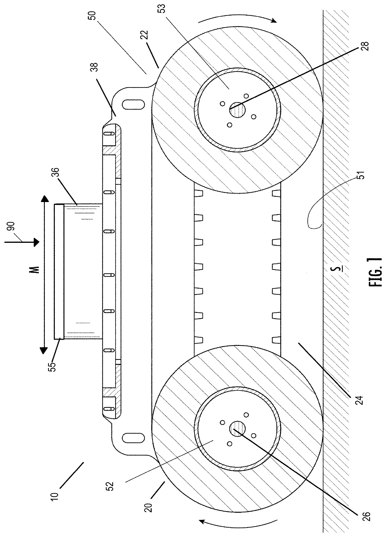
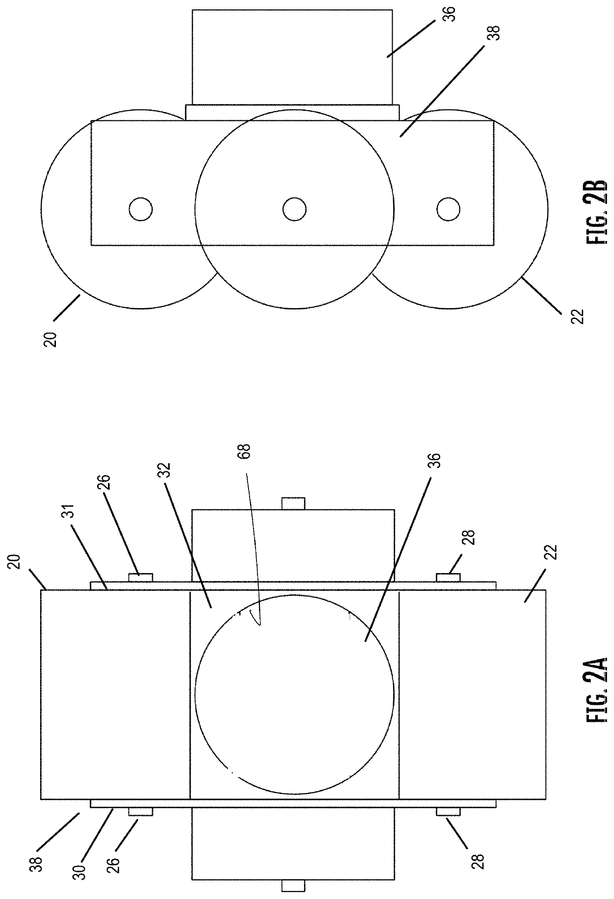
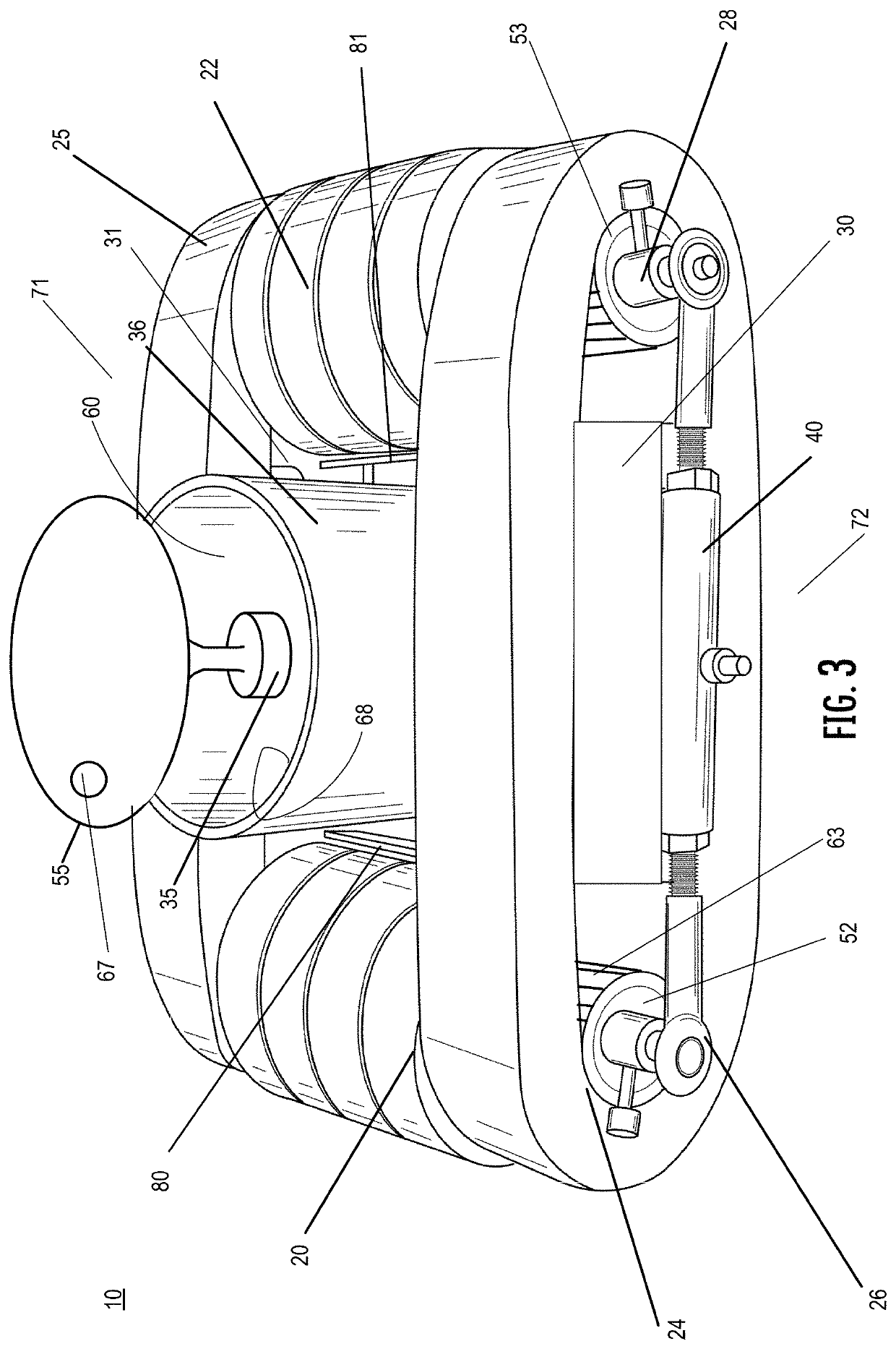
[0016]Referring to FIGS. 1-5, a device or apparatus 10 has a reservoir 36 filled with fluid couplant 37 and mounted to a frame 38 in which first and second rollers 20, 22 are attached to form a rolling seal assembly 50 together with resilient roller tracks 24, 25 resulting in a rolling seal 51 to prevent the egress of fluid couplant 37 from the reservoir 36 from escaping, even while the device 10 is moved along a surface S. The first roller 20 is mounted to first axle 26 of a first roller shaft 52 and the second roller 22 is mounted to a second axle 28 with a second roller shaft 53. The first axle 26 and the second axle 28 are connected to each other via a rod 40, 41 on either side of the device 10. The rods 40, 41 are mounted to the frame 38. The first and second rollers 20, 22 are flanked by a first roller track 24 and a second roller track 25 rotatable about first and second roller shafts 52, 53. The resilient roller tracks 24, 25 may also be a toothed belt (see FIG. 1) and the f...


PUM


Abstract

A device including a reservoir filled with fluid, a frame, and a resilient rolling seal to prevent the fluid from reservoir from escaping, even while the device is moved along a surface. The purpose of this device is to deploy a sensor which is housed within the reservoir. The device is thus capable of maintaining a reservoir of fluid around a sensor or probe and allow the sensor or probe to remain immersed in the fluid, while also remaining in contact with the surface in which the device is moved along. The sensor preferably resides in a fluid couplant of the device. Because the fluid and the sensor reside in the reservoir and because that reservoir is effectively sealed, there is very little loss of fluid, and the amount of fluid needed to conduct testing is dramatically decreased.

Description


Claims


Application Information

Patent Timeline
Owner MAGGIO SAM
Features
  • R&D
  • Intellectual Property
  • Life Sciences
  • Materials
  • Tech Scout
  • Unparalleled Data Quality
  • Higher Quality Content
  • 60% Fewer Hallucinations
Learn More