Supercharge Your Innovation With Domain-Expert AI Agents!

Hydraulic System

a technology of hydraulic system and actuator, applied in mechanical equipment, couplings, constructions, etc., can solve the problems of requiring more precision on the part of the operator and good (fine) flow control, and achieve the effect of faster actuator operation and greater actuator control

Active Publication Date: 2011-01-20
J C BAMFORD EXCAVATORS LTD
View PDF12 Cites 0 Cited by
  • Summary
  • Abstract
  • Description
  • Claims
  • Application Information

AI Technical Summary

Benefits of technology

[0010]The present invention utilizes the principle of varying the fluid flow to the control valve, by relieving excess fluid provided by a fixed capacity pump, or reducing the output of a variable capacity pump, depending on the load pressure, but enables a greater flow of fluid through the control valve e.g. for faster actuator operation, by delivering the control pressure at the load pressure to the flow control apparatus, or a lesser flow of fluid to the control valve e.g. for slower more controlled actuator operation, by delivering the control pressure to the flow control apparatus at the modified pressure less than the load pressure.
[0011]Thus there is no need to compromise the design of the control valve which may thus permit the greatest fluid flow to the actuator (or actuators) for a particular control valve setting, as the system pressure will lead to the maximum fluid flow through the control valve, and in the case where slower fine actuator control is required, by operating the pressure control device so that the control pressure which is delivered to the flow control apparatus is the modified load pressure, so for the same load and control valve setting, less fluid will flow through the control valve allowing greater actuator control by the control valve.

Problems solved by technology

As there is generally a linear relationship between movement of the manual control and flow through the control valve, this means that good (fine) flow control can only be achieved in response to small movements of the manual control, thus requiring more precision on the part of the operator.

Method used


Image

  • Hydraulic System
  • Hydraulic System
  • Hydraulic System

Examples


Embodiment Construction

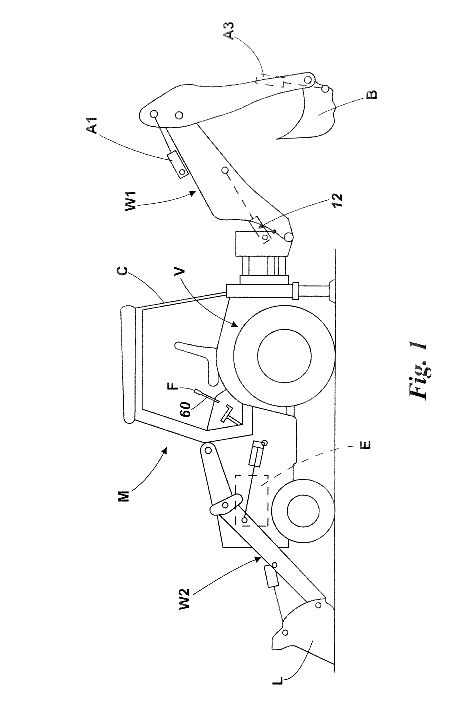
[0027]Referring to FIG. 1 there is shown a working machine M which has a body V which mounts a working arm W1, W2. The machine M of FIG. 1 has both a working arm W1 for excavating operations, at the rear in the example, and a working arm W2 for loading operations, at a front in the example.

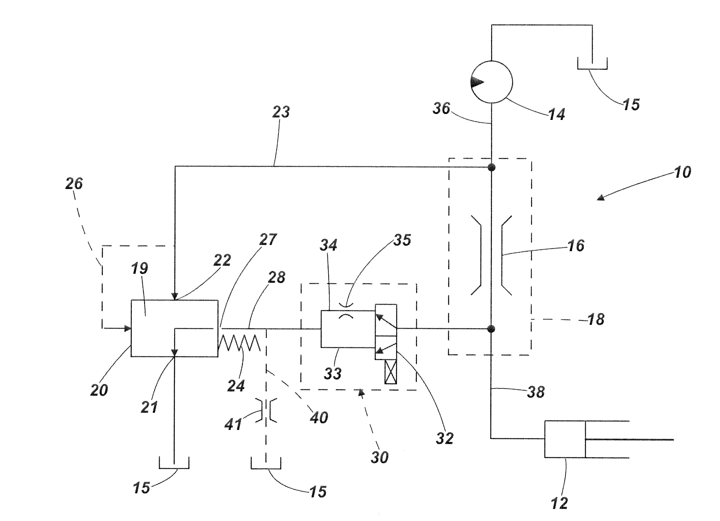
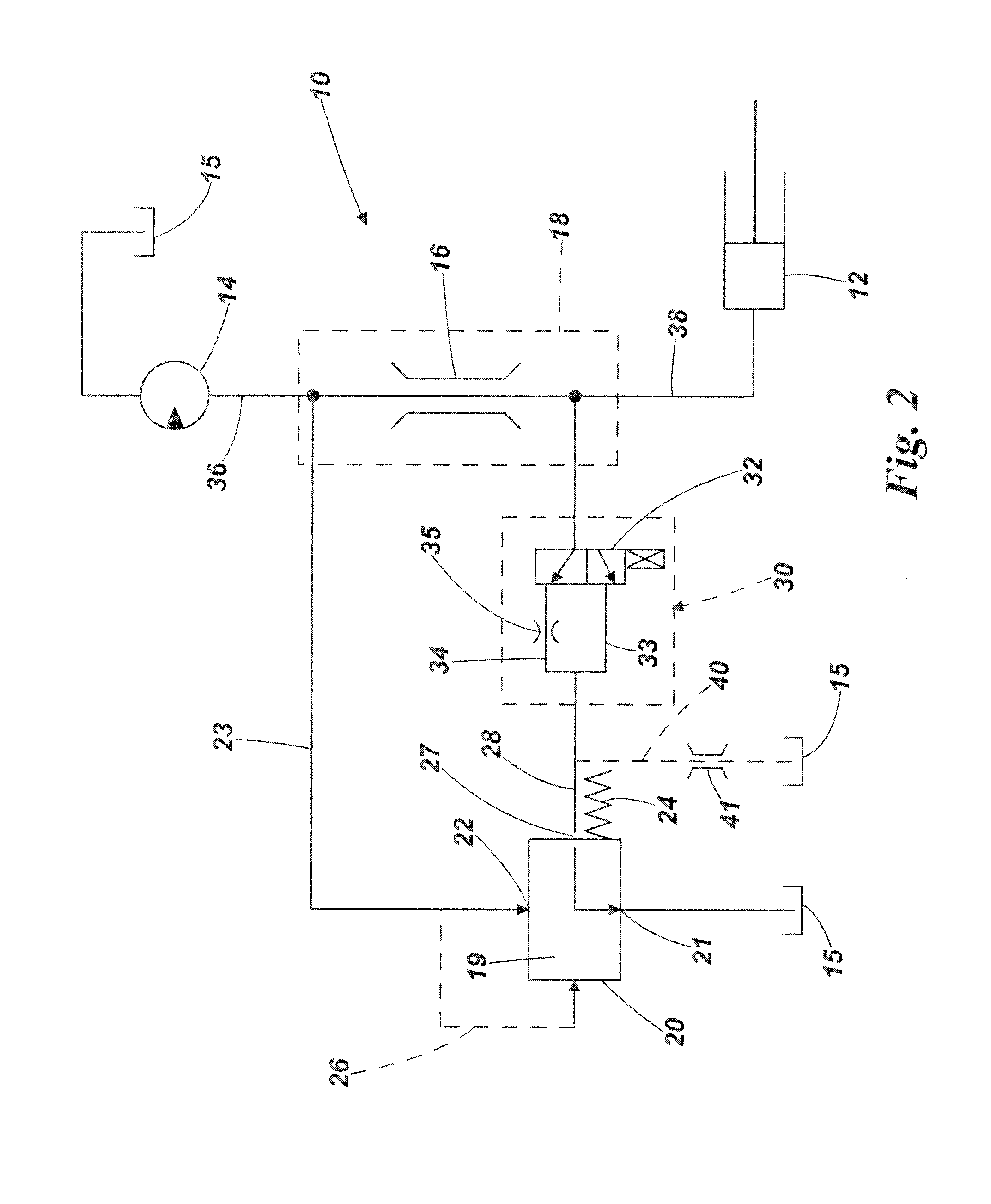
[0028]Embodiments of the invention will now be described more particularly in relation a hydraulic system 10 for operating a lifting actuator 12 of the excavating arm W1, which when extended raises the excavating arm W1 relative to the body B. However it will be appreciated that a hydraulic system in accordance with the invention may be used to operate other actuators which operate the excavating arm W1 and / or an implement e.g. bucket B carried by the excavating arm W1, e.g. as shown at A2, and A3. Further alternatively a hydraulic system in accordance with the invention may be used to operate actuators of the loading arm W2 or loading implement L carried thereby.

[0029]Referring to FIG. 2 a first ...


PUM


Abstract

A hydraulic system for an operator controlled machine, the system including at least one actuator for moving a machine component, a source of pressurized fluid for delivering pressurized fluid at a system pressure to a control valve which is operable under operator control, to control the flow of fluid from the source to the actuator at a load pressure, along a load pressure path, a flow control apparatus for controlling the flow of fluid from the source to the control valve, the flow control apparatus including an actuating part which is biased by a resilient device to a condition in which the flow control apparatus provides for a maximum flow of fluid to the control valve, actuating part movement by the resilient device being resisted by system pressure fluid and being supported by fluid at a control pressure, the control pressure being derived from the load pressure, and wherein the system includes a pressure control device to which the load pressure is communicated, the pressure control device being operated under operator control either to deliver the control pressure to the flow control device at load pressure or a modified pressure which is less than the load pressure.

Description

BACKGROUND TO THE INVENTION[0001]This invention relates to a hydraulic system and more particularly to a hydraulic system for effecting the operation of at least one actuator of a working machine.Description of the Prior Art[0002]Hydraulic systems are known for use in working machines which include an actuator for moving a machine component such as a working arm which carries a working implement such as for example only, an excavating bucket, relative to a machine body.[0003]Such systems typically include a source of pressurized hydraulic fluid, typically a pump driven from an engine of the machine, and a control valve which may include one or more spools or the like, to control the flow of fluid provided by the pump, to a or a respective one of one or more downstream actuators, the pressure downstream of the control valve being a load pressure, or where there are a plurality of spools or the like which are operated simultaneously, an maximum load pressure.[0004]In one example, the ...

Claims


Application Information

Patent Timeline
Patent Type & Authority Applications(United States)
IPC IPC(8): F15B13/00
CPCE02F3/963E02F9/2235E02F9/2296F15B2211/20538F15B2211/20553F15B2211/50536F15B2211/5753F15B2211/6051F15B2211/6057F15B2211/6346F15B2211/651F15B2211/654F15B11/165F15B11/166E02F9/2228E02F9/2203E02F9/2225F15B11/032F15B11/042F15B13/042
Inventor NAROTHAM, HARISHCHANDRA M.SMITH, MARTIN R.
Owner J C BAMFORD EXCAVATORS LTD
Features
  • R&D
  • Intellectual Property
  • Life Sciences
  • Materials
  • Tech Scout
  • Unparalleled Data Quality
  • Higher Quality Content
  • 60% Fewer Hallucinations
Learn More