
Headgear assembly with semi-rigid side arms

a technology of side arms and headgear, which is applied in the direction of respiratory masks, respirators, etc., can solve the problems of affecting the use of the headgear, the straps of the headgear becoming tangled, and the headgear having relatively little structur

Pending Publication Date: 2021-06-24
FISHER & PAYKEL HEALTHCARE LTD
View PDF6 Cites 6 Cited by
  • Summary
  • Abstract
  • Description
  • Claims
  • Application Information

AI Technical Summary

Benefits of technology

The patent describes a headgear assembly for use in respiratory therapy that includes a pair of semi-rigid side arms. The side arms have an adjustment mechanism that allows for movement between a single interface and the user's head. The headgear assembly also includes a top strap, rear strap, chin strap, and a connecting member between the interface and the side arms. The headgear assembly can be used with a variety of patient interfaces and provides a comfortable and secure fit. The technical effects of the invention include improved comfort, adjustable straps, and a more secure and stable seal with the patient interface.

Problems solved by technology

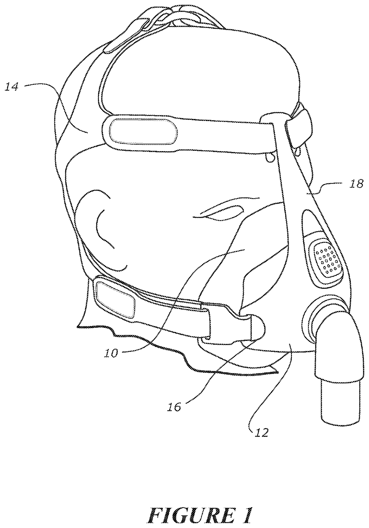
Typically, a mask creates at least a substantial “seal” on or around the nose and / or the mouth of a user while a cannula does not provide a seal but provides a delivery pathway for supplemental respiratory gas delivery.
The use of such a material results in the headgear having relatively little structure when not being worn.
This lack of structure can give rise to the straps of the headgear becoming tangled, which in turn can make it difficult for a user to don the headgear and breathing apparatus.
Such systems also require a reasonable level of user interaction and, as a result, is prone to misuse or mis-adjustment (e.g., over-tightening).
As a practical matter, micro-adjustment of such systems is difficult and time-consuming to accomplish.
This can result in the headgear stretching over, and applying pinching forces to, the user's head, which can be uncomfortable.

Method used


Image

  • Headgear assembly with semi-rigid side arms
  • Headgear assembly with semi-rigid side arms
  • Headgear assembly with semi-rigid side arms

Examples


Embodiment Construction

[0049]Embodiments of systems, components and methods of assembly and manufacture will now be described with reference to the accompanying figures, wherein like numerals refer to like or similar elements throughout. Although several embodiments, examples and illustrations are disclosed below, it will be understood by those of ordinary skill in the art that the inventions described herein extends beyond the specifically disclosed embodiments, examples and illustrations, and can include other uses of the inventions and obvious modifications and equivalents thereof. The terminology used in the description presented herein is not intended to be interpreted in any limited or restrictive manner simply because it is being used in conjunction with a detailed description of certain specific embodiments of the inventions. In addition, embodiments of the inventions can comprise several novel features and no single feature is solely responsible for its desirable attributes or is essential to pra...


PUM


Abstract

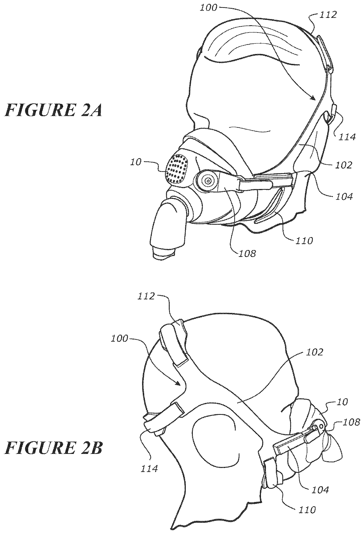
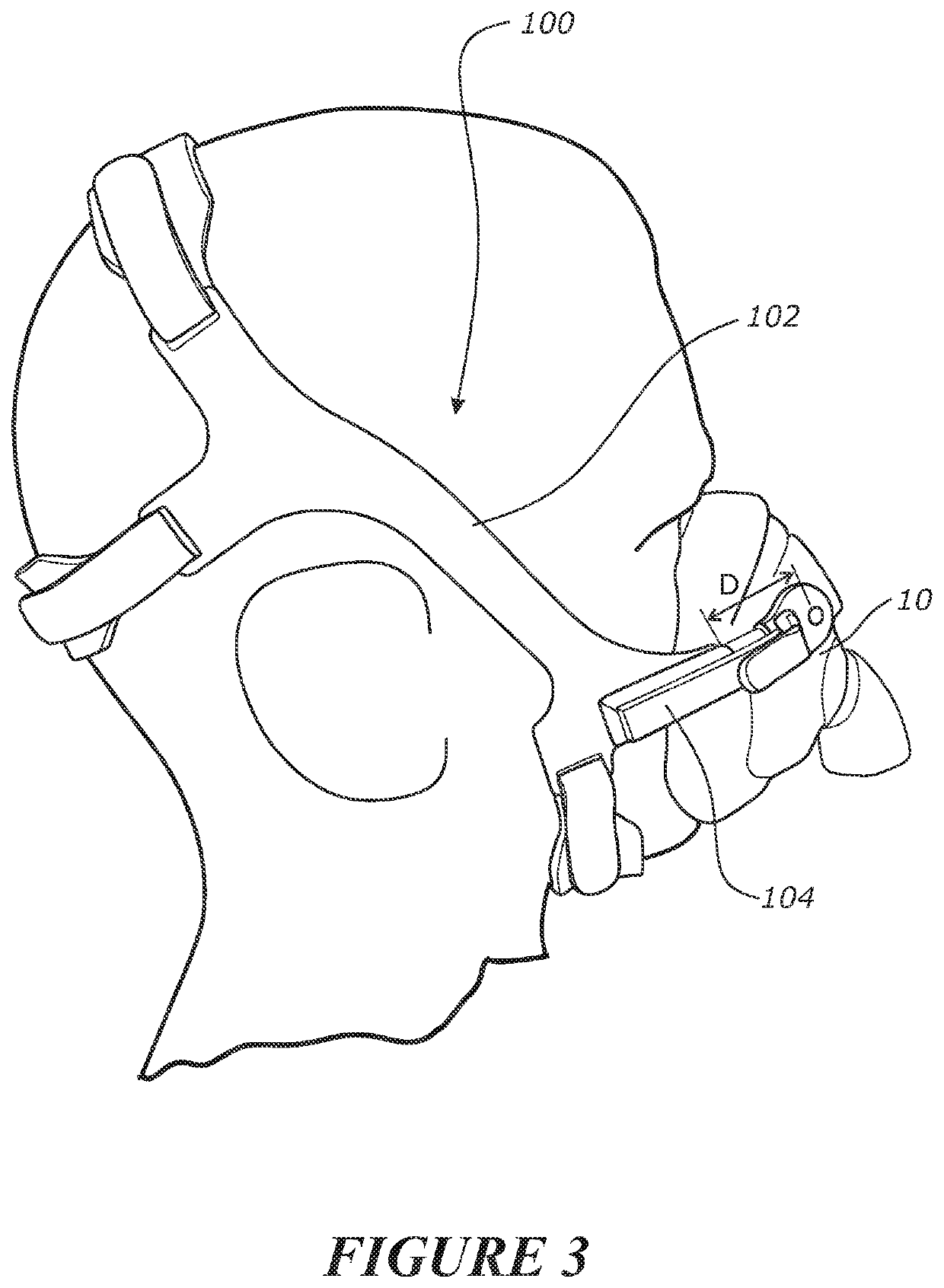
A headgear assembly can include a pair of opposing, semi-rigid side arms. Each side arm can be pivotally coupled to an interface at a single location. Each side arm can extend from the single location across the user's cheeks and above the user's ears in use. The headgear assembly can include a top strap coupled to the pair of opposing, semi-rigid side arms, the top strap configured to extend around the top of a user's head. The headgear assembly can include a rear strap coupled to the pair of opposing, semi-rigid side arms, the rear strap configured to extend around the rear of a user's head. The headgear assembly can include a chin strap coupled to the pair of opposing, semi-rigid side arms, the chin strap configured to extend around the user's chin.

Description

BACKGROUNDField[0001]The present disclosure relates to headgear assemblies for use in respiratory therapy. More particularly, certain aspects of the present disclosure relate to headgear assemblies including rigid side arms which are connected to the interface.Description of Related Art[0002]The treatment of respiratory ailments or conditions with therapies, such as NIV, Bi-level or CPAP, involves the delivery of pressurized air to the airways of a human via a conduit and a breathing apparatus (e.g., a mask or cannula). Typically, a mask creates at least a substantial “seal” on or around the nose and / or the mouth of a user while a cannula does not provide a seal but provides a delivery pathway for supplemental respiratory gas delivery.[0003]A result of creating this “seal” is that the combination of the enclosure area of the breathing apparatus and its internal pressure creates a resulting force that attempts to push the breathing apparatus off of the face. To counteract this force,...

Claims


Application Information

Patent Timeline
Patent Type & Authority Applications(United States)
IPC IPC(8): A61M16/06
CPCA61M16/0694A61M16/0683A61M16/0605
Inventor TEBBUTT, ADAM ALEXANDERSTEPHENSON, MATTHEW ROGERWALLS, BRUCE MICHAELPEREIRA, PRIYANKA FERDINANDFREESTONE, PAUL MATHEWBORNHOLDT, MELISSA CATHERINEHOCKING, JAKE BAKERFARROW, ABBY REBECCAHIPOLITO, CHRIS ONIN LIMPIN
Owner FISHER & PAYKEL HEALTHCARE LTD
Learn More