Rotary latch device

a latch device and rotary technology, applied in the direction of flanged joints, pipe laying and repair, borehole/well accessories, etc., can solve the problems of affecting affecting the safety of personnel, and requiring personnel to be exposed to potentially hazardous conditions. , to achieve the effect of simplifying the connection and disconnection of the first mandrel

Inactive Publication Date: 2021-06-24
OIL STATES ENERGY SERVICES
View PDF0 Cites 0 Cited by
  • Summary
  • Abstract
  • Description
  • Claims
  • Application Information

AI Technical Summary

Benefits of technology

[0004]A latching assembly to couple a first mandrel to a second mandrel is disclosed. The latching assembly includes a plurality of wedge members disposed circumferentially and a guide plate. Each wedge member may include a semi-annular wedge body, an upper engagement lip, a lower engagement lip, and a guide pin. The guide plate may include a plurality of guide slots to translate and rotate the plurality of wedge members via the respective guide pins. Because the plurality of wedge members can be translated and rotated to lock and release the first mandrel to and from the second mandrel, the latching assembly can simplify the connection and disconnection of a first mandrel with the second mandrel.

Problems solved by technology

However, one drawback of conventional interfaces is that aligning and coupling a tool to the surface interface often requires personnel to be exposed to potentially hazardous conditions.
Further, tools may be improperly aligned and / or incompletely secured to conventional interfaces.
Improper alignment or incomplete coupling can lead to leakage or a risk of blowout.

Method used


Image

  • Rotary latch device
  • Rotary latch device
  • Rotary latch device

Examples


Embodiment Construction

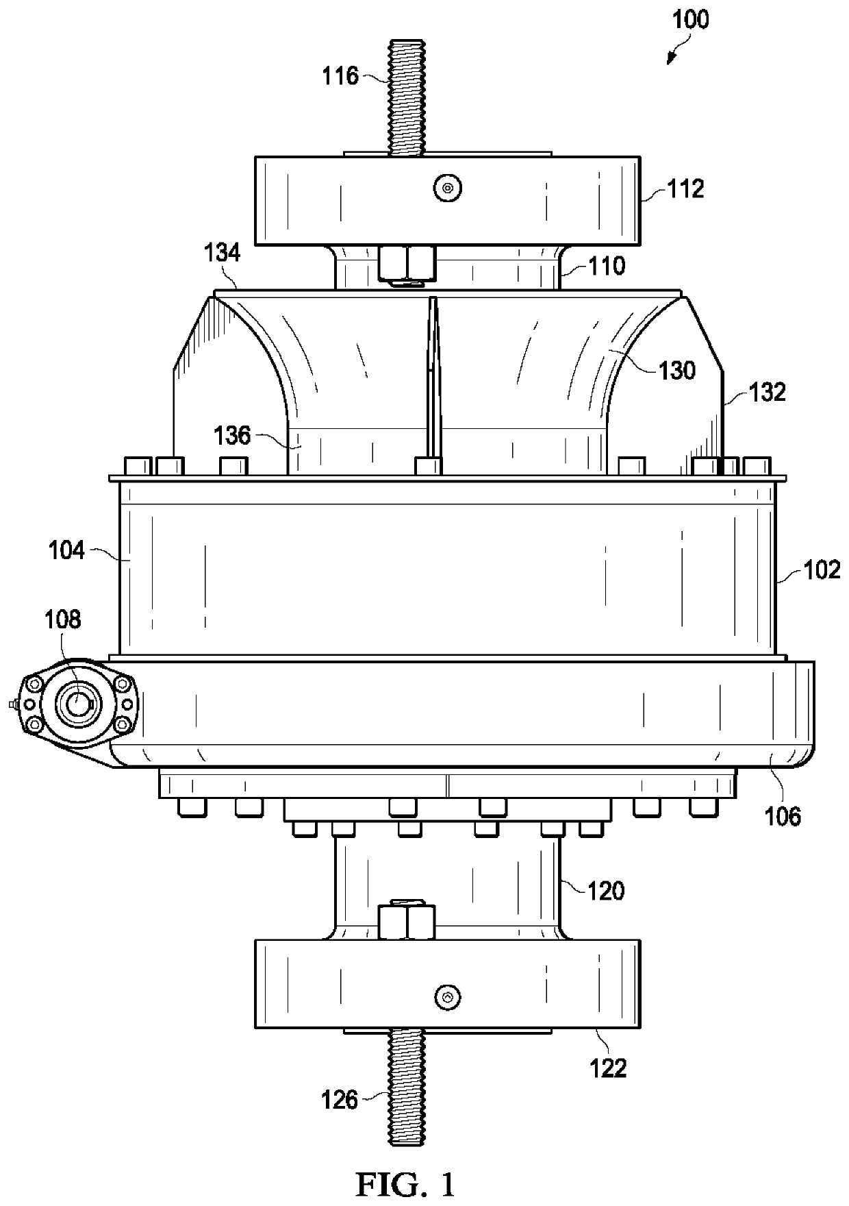
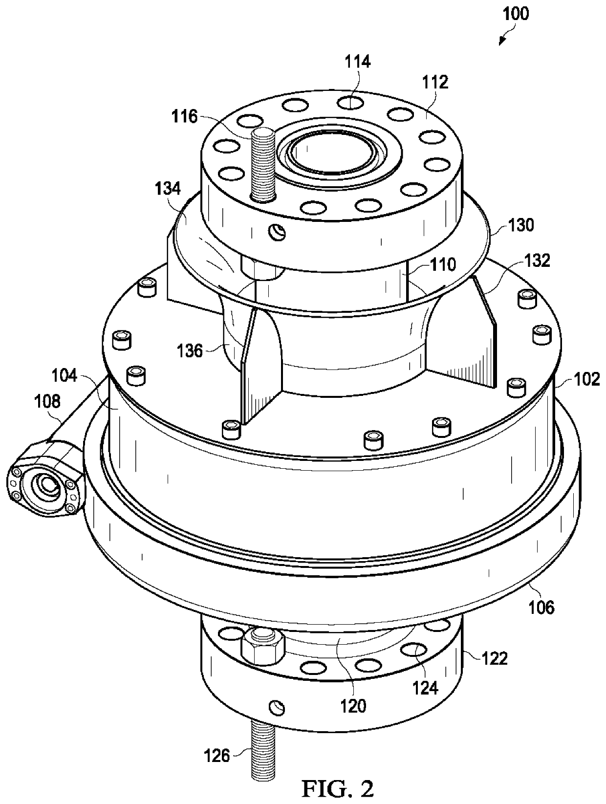
[0015]FIG. 1 is an elevation view of an embodiment of a rotary latch device 100. FIG. 2 is an isometric view of the rotary latch device 100 of FIG. 1. With reference to FIGS. 1 and 2, the rotary latch device 100 can receive a tool mandrel 110 and latch and / or engage the tool mandrel 110 to a wellhead connection mandrel 120.

[0016]In the depicted example, the rotary latch device 100 can be coupled to the wellhead connection mandrel 120. As illustrated, the wellhead connection mandrel 120 can be coupled to a lower portion 106 of the device housing 102. In some applications, the wellhead connection mandrel 120 can allow access to a wellbore via a wellhead in fluid communication with the wellhead connection mandrel 120. The wellhead connection mandrel 120 can be coupled to downstream wellbore components with a flange 122. Fasteners 126 can extend through fastener holes 124 to secure the flange 122 to downstream wellbore components. As described herein, the rotary latch device 100 can be ...


PUM


Abstract

A latching assembly to couple a first mandrel to a second mandrel is disclosed. The latching assembly includes a plurality of wedge members disposed circumferentially and a guide plate. Each wedge member may include a semi-annular wedge body, an upper engagement lip, a lower engagement lip, and a guide pin. The guide plate may include a plurality of guide slots to translate and rotate the plurality of wedge members via the respective guide pins. Because the plurality of wedge members can be translated and rotated to lock and release the first mandrel to and from the second mandrel, the latching assembly can simplify the connection and disconnection of a first mandrel with the second mandrel.

Description

TECHNICAL FIELD[0001]The present disclosure relates generally to wellhead systems, and, more particularly, to latching devices for use with wellhead systems.BACKGROUND[0002]Tools and equipment can be used for a wide variety of purposes with oil and gas wells. For example, wireline tools can lower instruments into a wellbore on the end of a wireline cable to measure wellbore properties or perform operations within the wellbore. During operation, tools and equipment can be attached and removed from an oil and gas well.[0003]Wellhead systems can provide a surface interface to allow tools and equipment to be coupled with an oil and gas well. For example, a wireline tool can be aligned with and coupled to a wellhead system. However, one drawback of conventional interfaces is that aligning and coupling a tool to the surface interface often requires personnel to be exposed to potentially hazardous conditions. Further, tools may be improperly aligned and / or incompletely secured to conventio...

Claims


Application Information

Patent Timeline
Patent Type & Authority Applications(United States)
IPC IPC(8): E21B33/03F16L23/12F16L23/04
CPCE21B33/03F16L23/04F16L23/12F16L1/26F16L23/003
Inventor LIVINGSTON, JIMMYMCGUIRE, BOB
Owner OIL STATES ENERGY SERVICES
Why Eureka
Try Eureka