Magnetic fixture

a technology of magnetic fixture and fixing plate, which is applied in the direction of grinding drive, grinding machine components, manufacturing tools, etc., can solve the problems of inability to achieve the production volume required, process is generally unacceptably long for integration into the production line environment, and is too slow for hardened engineering components such as case-carburized gearsets. to achieve the effect of preventing knocking, simplifying subsequent identification, and facilitating connection and disconnection

Active Publication Date: 2017-01-24
REM TECHNOLOGY INC
View PDF30 Cites 7 Cited by
  • Summary
  • Abstract
  • Description
  • Claims
  • Application Information

AI Technical Summary

Benefits of technology

[0016]The present invention addresses these problems by the use of a magnet to retain a metal workpiece during a media based finishing operation. In this manner simplified connection and disconnection may be achieved and the workpieces can be prevented from knocking, and damaging one another even in a batch process. Furthermore, the magnet can be used to keep particular components together and simplify subsequent identification. Magnets can be quickly and easily released with little additional process time and are generally sufficiently strong to withstand the forces applied in e.g. vibratory bowls.
[0022]In an embodiment of the invention, the drive arrangement may comprise a force limiting control to limit a force applied to the magnetic fixture to a value lower than a retention force between the magnetic fixture and the workpiece. Active control of the drive arrangement in this manner may serve to avoid workpieces becoming separated from their fixtures. The skilled person will understand that various indicators can be used to prevent disengagement including contact and proximity sensors between the workpiece and the fixture. In response to excess force or (imminent) disconnection of a workpiece, the drive arrangement may be stopped or its speed reduced.
[0026]In a particular embodiment of the invention, the magnet may be substantially embedded within the body. This allows the magnet to be protected by the body from exposure to the media. It also may prevent direct contact between the magnets and the workpiece. The magnet or magnets may be located within a bore or cavity of the body and subsequently sealed. Alternatively, they may be incorporated or encapsulated within a plastic body during a manufacturing or moulding procedure. Most preferably, the body has a smooth outer surface without openings or locations where media may lodge.
[0028]Although the fixture may have a flat face for receiving the workpiece, in another preferred embodiment of the invention, the body may comprise a profiled seat. The seat is preferably of an at least partially complementary shape to the surface of the workpiece which it is to engage. By providing a profiled seat, the exact location of the workpiece may be better determined or maintained. Furthermore, accidental disconnection may be prevented since lateral forces may be resisted by mechanical engagement of the seat and workpiece. Such a seat may provide a certain amount of mechanical interference fit between the fixture and the workpiece. Nevertheless, the axial retaining force preventing separation of the workpiece is preferably provided primarily by the magnetic force of attraction. Preferably the magnetic force provides more than 60% of the axial retaining force, most preferably more than 90% of such force. The seat may also be provided with a seal such as an O-ring, lip, ridge or the like in order to prevent ingress of media or chemicals between the workpiece and the fixture.
[0034]Preferably, the workpiece is retained substantially only by the magnet and is not significantly retained by other means. In use, an operator thus need only separate the workpiece from the magnet by the force required to overcome magnetic attraction. Additional locking and fixturing is not required and the process time associated with fixturing is significantly reduced.

Problems solved by technology

As yet however such processes are not able to achieve the production volumes required by the industry in a cost-effective manner.
These procedures are generally recognized as being, too slow for use on hardened engineering components such as case-carburized gearsets.
Such a process is generally unacceptably long for integration into a production line environment.
This can reduce the processing time per part but it can unfortunately also lead to components knocking against one another, causing damage and resulting in scrapped parts.
Furthermore, it is not convenient for components that have been individually identified or matched.
For such components, batch finishing is generally not suitable as it requires complicated marking and subsequent identification of all components.
This is however only practical with a small number of partitions whereby relatively few gear-sets can be finished in each machine.
Another problem is that parts are prone to lodge in corners of the bowl, resulting in a non-uniform finish and scrapping of the part.
Such an arrangement of individual containers would not appear practical in keeping large numbers of components separate from one another.
It is also doubted that it would be effective on metal components which would themselves be attracted by the magnets.
For production line manufacturing, any fixturing device must be easy to connect and release, since these procedures will usually add to the overall process time.
Fixturing devices of this type are not however commonplace in media based processes and do not appear readily suited for such use.
The media used is often relatively small and can become easily lodged in screw threads, clamps and tool openings such as screw and bolt heads.
Additionally, the finishing process itself can be detrimental to such fixtures making them difficult to open.
For these reasons, conventional mechanical fixtures are not ideally suited for use in media based finishing environments.
These devices would also not lend themselves to use in a media based finishing environment, where the workpiece is substantially surrounded by and free-floated in the media.
Operating with active aqueous chemistry would also pose a serious safety risk.
Although some reduction in contact damage between components may be achieved, the arrangement does not separately retain matched components and is not suitable for all shapes and size of workpiece.

Method used


Image

  • Magnetic fixture
  • Magnetic fixture
  • Magnetic fixture

Examples


first embodiment

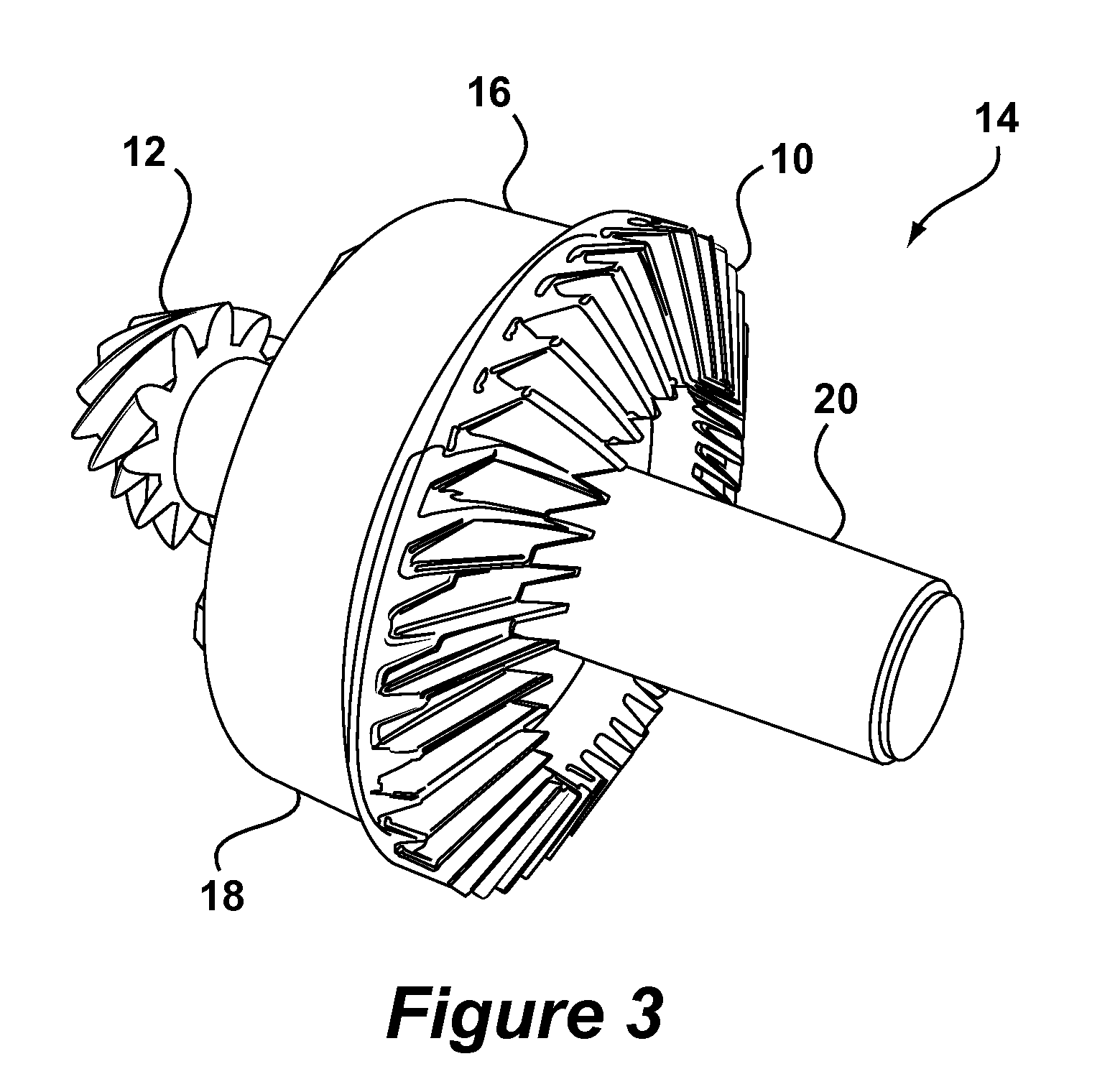
[0053]FIG. 3 shows a fixture 14 according to the invention. The fixture 14 comprises a body 16 formed of a disk 18 and a shaft 20 onto which the ring 10 and pinion 12 are respectively connected. In the depicted embodiment, the body 16 is formed of a single piece of Delrin™.

[0054]FIGS. 4A and 4B show exploded perspective views of the fixture 14 of FIG. 3 from two different angles. As can be seen, the disk 18 has a top face 22 and a bottom face 24. Bores 26 in the top face 22 extend through the disk to a distance of about 1.5 mm from the bottom face 24. Magnets 28 are received within the bores 26, which are closed by plugs 30 of Delrin™. The magnets 28 are formed of neodymium material (Nd2Fe14B) and each can exert a retaining force of around 4 Kg when acting through the material of the bottom face 24 of the disk 18 in this manner. Five bores 26 are spaced around the circumference of the disk 18, of which four can be seen in the Figures. Furthermore, a central bore 36 through the shaft...

second embodiment

[0057]In an alternative (non-illustrated) embodiment, the fixture may be allowed to tumble freely in a bowl or tub. This may be the case where impact between workpieces is not a significant issue but nevertheless, pairing of matched components is desired. In the case of a freely tumbling version, it could also be desirable to locate both a ring and a pinion on the same face of the fixture in order to promote tumbling. Such an arrangement is shown below in the context of the invention.

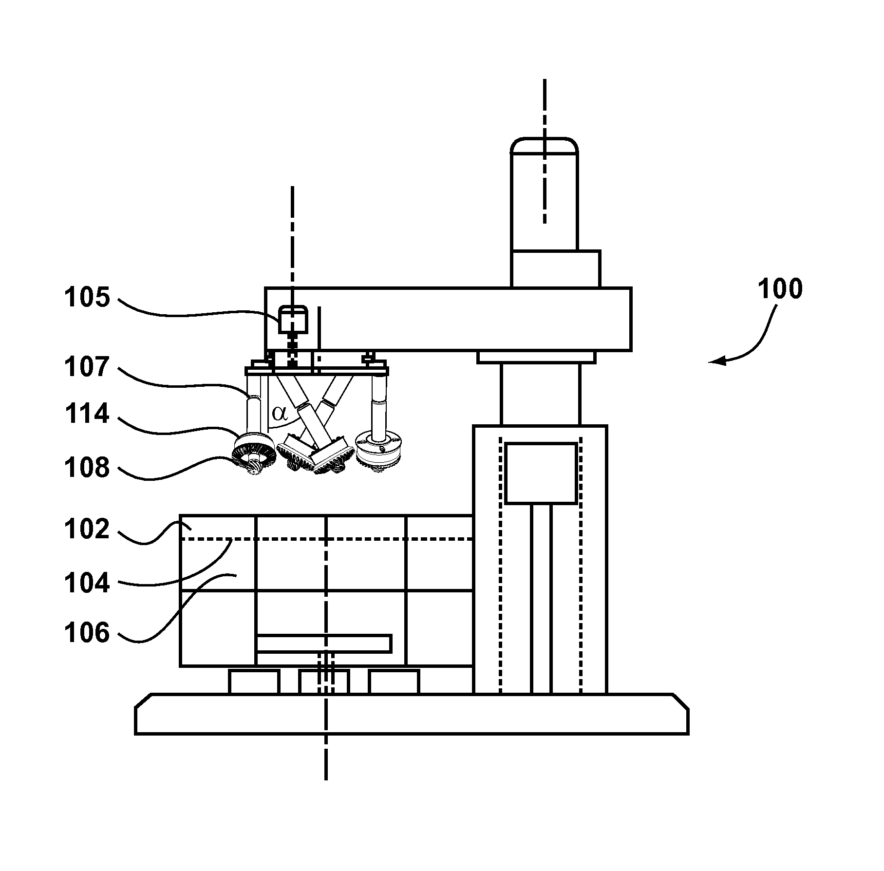
[0058]A second embodiment of the invention is shown in FIG. 6 for use in drag-finishing. In the description of this embodiment, like reference numerals preceded by 100 will be used to denote similar features.

[0059]According to FIG. 6, there is shown a drag-finishing machine 100 having a bowl 102 containing non-abrasive media 104. A drive arrangement 105 causes rotation of arms 107 to force workpieces 108 through the media 104. Each workpiece 108 is carried by a fixture 114. The arms 107 rotate together ...


PUM

PropertyMeasurementUnit
Raaaaaaaaaaa
distanceaaaaaaaaaa
forceaaaaaaaaaa

Abstract

A fixture is provided for retaining a metal workpiece for contact by finishing media during operation of a media based finishing operation. The fixture comprises a body and a magnet for retaining the workpiece in contact with the body. By use of super-magnetic materials a significant holding force may be achieved.

Description

BACKGROUND OF THE INVENTION[0001]1. Field of the Invention[0002]The invention relates generally to fixturing arrangements and more particularly to fixturing arrangements for releasably mounting metal components to be treated in a media based finishing process. The invention also relates to methods of finishing engineering components in particular batch finishing where a large number of components are finished together.[0003]2. Description of the Related Art[0004]Procedures for producing a smooth surface finish on metallic components are generally well known. Such procedures include barrel tumbling, abrasive vibratory finishing, grinding, honing, abrasive machining and lapping. Examples of mechanical parts that may be finished using these procedures include splines, crankshafts, camshafts, bearings, gears, continuous velocity (CV) joints, couplings, and journals. Various advantages may be achieved by such finishing including a reduction in wear, friction, noise, vibration, contact fa...

Claims


Application Information

Patent Timeline
Patent Type & Authority Patents(United States)
IPC IPC(8): B24B31/02B24B31/06B24B41/06B23Q3/154B24B31/03B25B11/00B24B31/00
CPCB24B41/06B23Q3/1543B23Q3/1546B24B31/003B24B31/0224B24B31/064B25B11/002
Inventor SROKA, GARYEL-SAEED, OMER
Owner REM TECHNOLOGY INC
Why Eureka
Try Eureka