Hair styling appliance

a hair styling and hair technology, applied in the direction of curling irons, hair equipments, curling-tongs, etc., can solve the problems of heat damage to the hair

Pending Publication Date: 2021-07-22
DYSON TECH LTD
View PDF1 Cites 0 Cited by
  • Summary
  • Abstract
  • Description
  • Claims
  • Application Information

AI Technical Summary

Benefits of technology

[0022]In a preferred embodiment, the heating plate is flexible. Advantageously, use of an aluminium nitride ceramic heating element enables even transfer of thermal energy to a heating pl...

Problems solved by technology

Whilst a hair tress is gripped between closed arms of a hair straightener and subjected to high temperatures from the heated plates, there is a possibility of heat damage to the hair.
A...

Method used


Image

  • Hair styling appliance
  • Hair styling appliance
  • Hair styling appliance

Examples


Embodiment Construction

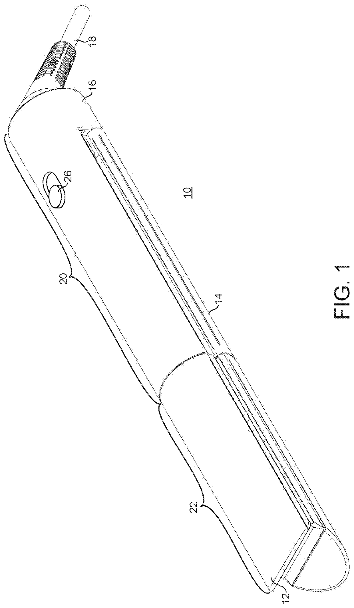
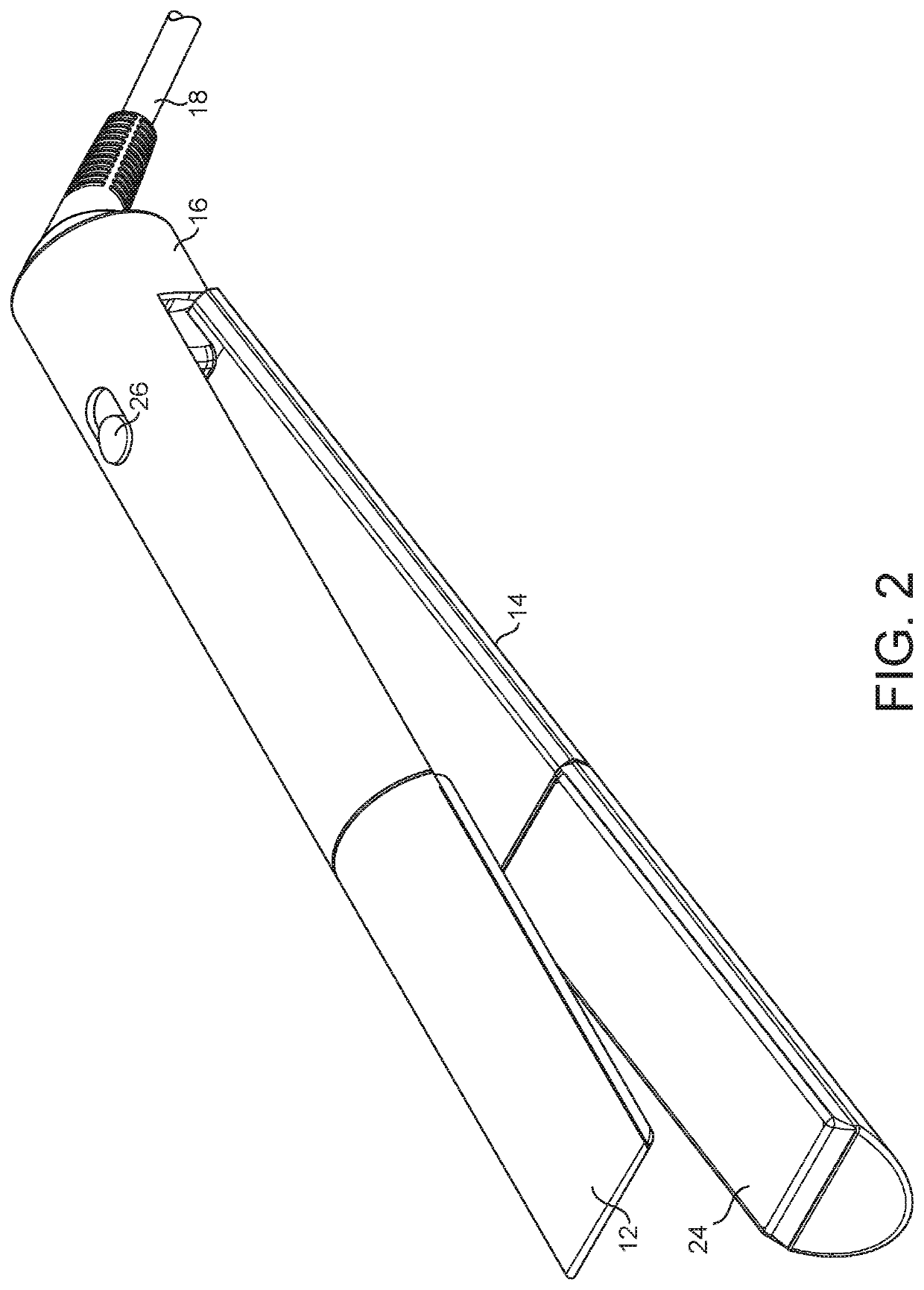
[0039]A hair straightener 10 shown in FIGS. 1 and 2 comprises a first arm 12 and a second arm 14 which are joined together at one end by a hinge 16. A power supply cable 18 is located at the hinge end of the hair straightener 10. The hair straightener 10 comprises a handle section 20 towards the hinge end of the arms and a hair contacting section 22 towards the distal end of the arms. The hair contacting section 22 comprises a heated plate 24 arranged on at least one of the facing surfaces of the hair contacting section 22. An actuation button 26 is positioned on the handle section 20 and the actuation button 26 switches on the power to the heated plate 24 and may also function to release the arms from a closed position.

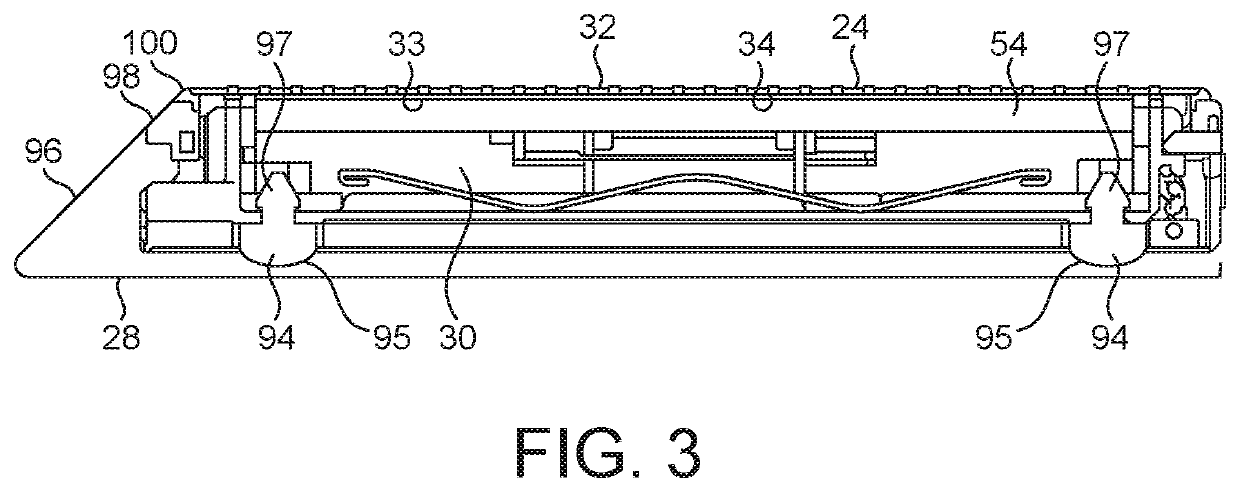
[0040]With reference to FIG. 3, a monocoque 28 provides a protective external casing around a heating assembly 30, whilst the heated plate 24 and several supporting components remain exposed. The heated plate 24 is formed as a single piece and has an exposed, smooth,...


PUM


Abstract

The present invention relates to a hair straightening apparatus having two arms pivotably coupled together and a heating plate on a facing side of at least one arm. A flexible protective rim substantially surrounds the periphery of a hair contacting surface of each heating plate.

Description

CROSS-REFERENCE TO RELATED APPLICATIONS[0001]This application is a national stage application under 35 U.S.C. 371 of International Application No. PCT / GB2018 / 052758 filed Sep. 27, 2018, which claims the priority of United Kingdom Application Nos. 1716664.6, 1716665.3, and 1716666.1, each filed Oct. 11, 2017, the entire contents of each of which are incorporated herein by reference.FIELD OF THE DISCLOSURE[0002]The present invention relates to a hair styling appliance. Heated hair styling appliances are designed to use the action of heat and, optionally mechanical means to form hair into a desired shape or style.BACKGROUND OF THE DISCLOSURE[0003]In particular the present invention relates to a hair straightener, also known as a hair styling iron. A hair straightener conventionally includes two articulated arms which are pivotally attached to each other at one end and a heated plate positioned on inner facing surfaces of the arms at the other end. The heated plates generally have hair ...

Claims


Application Information

Patent Timeline
IPC IPC(8): A45D1/04
CPCA45D1/04A45D2/001
Inventor COURTNEY, STEPHEN BENJAMINSMITH, ARRAN GEORGENICOLAOU, RICHARD DAVIDGROTRIAN, FREDERICK STUART
Owner DYSON TECH LTD
Why Eureka
Try Eureka