
Turbocharger including a turbine housing to reduce high cycle fatigue

a turbine housing and high cycle fatigue technology, applied in the field of turbochargers, can solve the problems of increased risk of high cycle fatigue failure of the turbine wheel, etc., and achieve the effect of increasing durability

Active Publication Date: 2022-10-25
BORGWARNER INC
View PDF10 Cites 0 Cited by
  • Summary
  • Abstract
  • Description
  • Claims
  • Application Information

AI Technical Summary

Benefits of technology

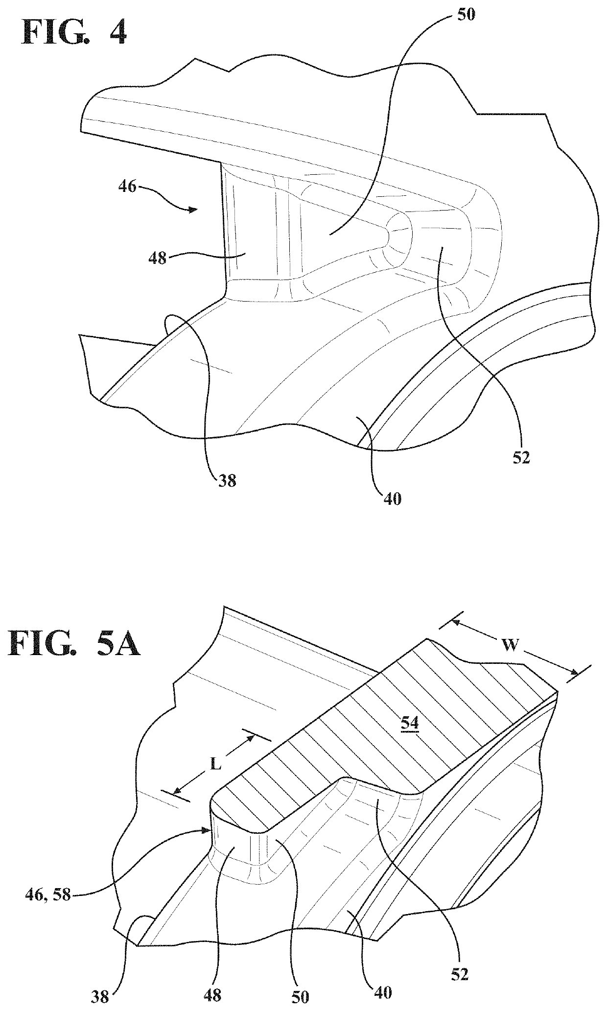
The present invention is a turbocharger designed to increase the durability of its turbine wheel by reducing high cycle fatigue caused by resonance with the flow of exhaust gas. It achieves this by shaping the pressure pulse to remove the spectral content that matches the natural frequency of the turbine wheel during operation. The design includes a first, second, and third tongue portions that extend from the volute wall of the turbine housing. The first tongue portion extends toward the second volute wall, the second tongue portion extends circumferentially about the axis, and the third tongue portion extends toward the second volote wall. This design helps to reduce the occurrence of resonance and high cycle fatigue, increasing the durability of the turbine wheel.

Problems solved by technology

Traditional tongues have been designed to optimize aerodynamic performance, but disadvantageously direct flow of exhaust gas toward the turbine wheel such that the turbine wheel may be subject to high cycle fatigue (HCF) which leads to failure of the turbine wheel.
Resonance of the turbine wheel leads to an increased risk of high cycle fatigue of the turbine wheel.
High cycle fatigue, in turn, may lead to cracks forming in the turbine wheel which have the potential to cause the turbine wheel to fail.
Therefore, the pressure pulse may decrease the durability of the turbine wheel by increasing the likelihood of failure resulting from high cycle fatigue caused by resonance of the turbine wheel.

Method used


Image

  • Turbocharger including a turbine housing to reduce high cycle fatigue
  • Turbocharger including a turbine housing to reduce high cycle fatigue
  • Turbocharger including a turbine housing to reduce high cycle fatigue

Examples


Embodiment Construction

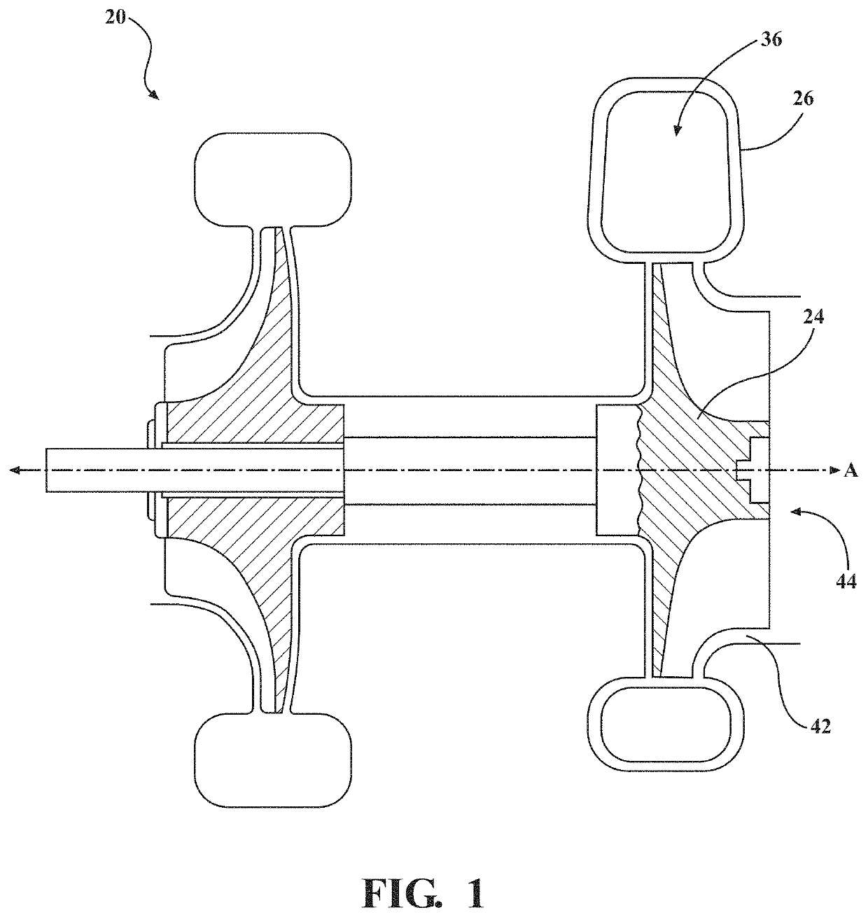
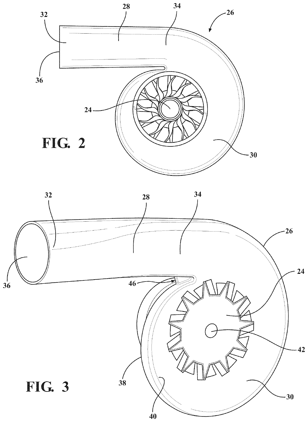
[0031]With reference to the Figures, wherein like numerals indicate like parts throughout the several views, a turbocharger 20 is shown schematically in FIG. 1. The turbocharger 20 delivers compressed air to an internal combustion engine and receives exhaust gas from the internal combustion engine. The turbocharger 20 includes a turbine wheel 24 rotatable about an axis A and a turbine housing 26 disposed about the turbine wheel 24. As shown in FIGS. 2 and 3, the turbine housing 26 includes an inlet portion 28 and a volute portion 30. The inlet portion 28 extends between a first end 32 and a second end 34 opposite the first end 32, and the inlet portion 28 defines a turbine housing inlet 36 configured to be in fluid communication with the internal combustion engine at the first end 32 for receiving exhaust gas from the internal combustion engine. The volute portion 30 extends from the inlet portion 28 at the second end 34 and extends circumferentially about the axis A. The volute por...


PUM


Abstract

A turbocharger includes a turbine wheel rotatable about an axis and a turbine housing disposed about the turbine wheel. The turbine housing has an inlet portion defining a turbine housing inlet and has a volute portion defining a turbine housing interior. The volute portion has a first volute wall, a second volute wall spaced from the first volute wall, and a tongue separating the turbine housing inlet and the turbine housing interior. The tongue has a first tongue portion extending from the first volute wall substantially toward the second volute wall along the axis, a second tongue portion extending from the first tongue portion substantially circumferentially about the axis, and a third tongue portion extending from the second tongue portion substantially toward the second volute wall along the axis to reduce high cycle fatigue of the turbine wheel.

Description

BACKGROUND OF THE INVENTION1. Field of the Invention[0001]The present invention relates generally to a turbocharger for delivering compressed air to an internal combustion engine and for receiving exhaust gas from the internal combustion engine.2. Description of the Related Art[0002]Turbochargers receive exhaust gas from an internal combustion engine and deliver compressed air to the internal combustion engine. Turbochargers are used to increase power output of the internal combustion engine, lower fuel consumption of the internal combustion engine, and reduce emissions produced by the internal combustion engine. Delivery of compressed air to the internal combustion engine by the turbocharger allows the internal combustion engine to be smaller, yet able to develop the same or similar amount of horsepower as larger, naturally aspirated internal combustion engines. Having a smaller internal combustion engine for use in the vehicle reduces the mass and aerodynamic frontal area of the v...

Claims


Application Information

Patent Timeline
Patent Type & Authority Patents(United States)
IPC IPC(8): F02B37/00F04D29/42F02B39/16F01D25/24
CPCF02B37/00F01D25/24F02B39/16F04D29/422F02B2039/162F05D2220/40F01D25/00F02C6/12Y02T10/12
Inventor TROXLER, PAULGRABOWSKA, DAVID GEORGE
Owner BORGWARNER INC
Learn More