
Nozzle blade design for a variable nozzle turbine

A nozzle blade, turbine technology, applied in the direction of mechanical equipment, blade support elements, combustion engines, etc., can solve the problems of pressure loss turbine efficiency and performance adverse effects, total pressure loss increase, etc.

Pending Publication Date: 2018-12-07
FORD GLOBAL TECH LLC
View PDF1 Cites 4 Cited by
  • Summary
  • Abstract
  • Description
  • Claims
  • Application Information

AI Technical Summary

Problems solved by technology

In this case the total pressure loss of the blade assembly increases due to increased end wall or turbine wheel losses
An increase in pressure loss in the system can adversely affect turbine efficiency and performance

Method used


Image

  • Nozzle blade design for a variable nozzle turbine
  • Nozzle blade design for a variable nozzle turbine
  • Nozzle blade design for a variable nozzle turbine

Examples


Embodiment Construction

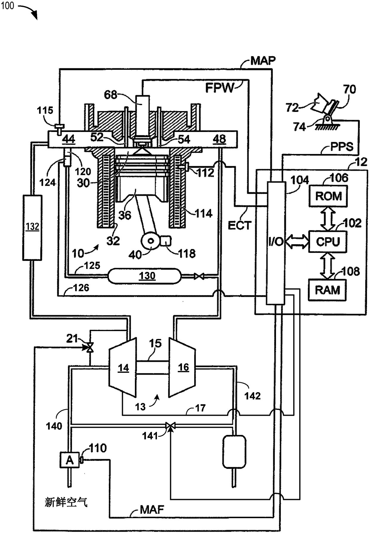
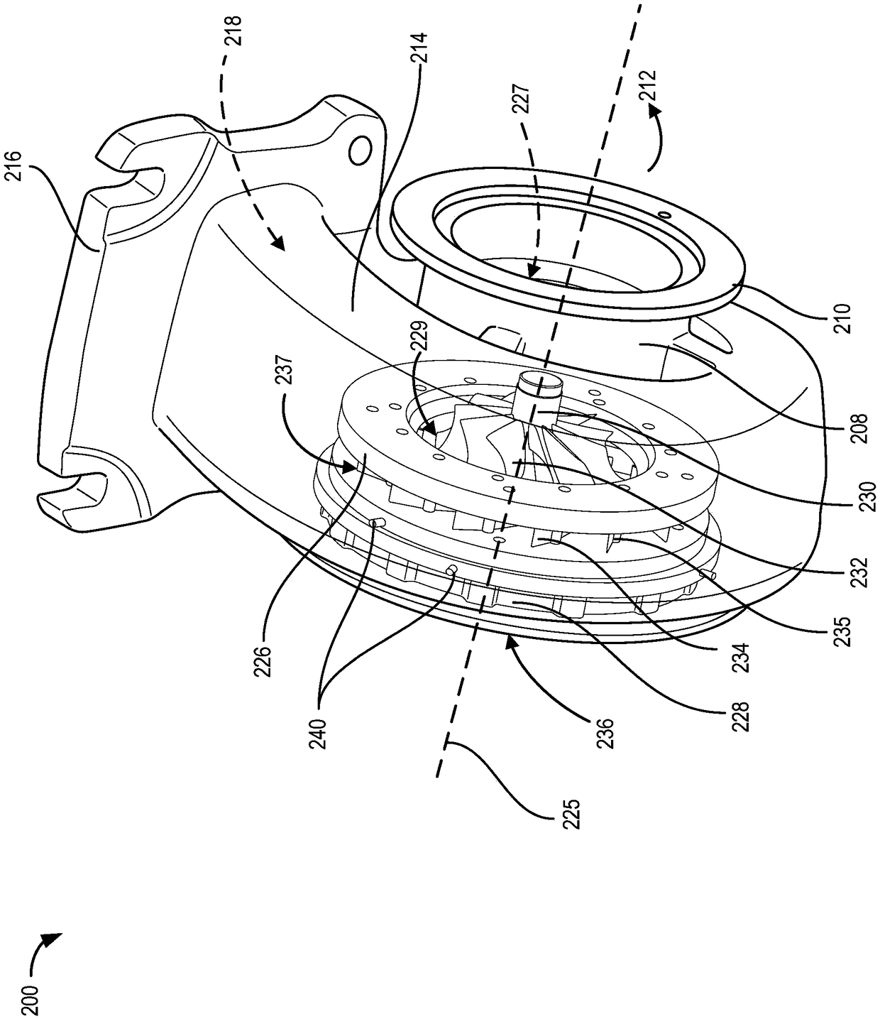
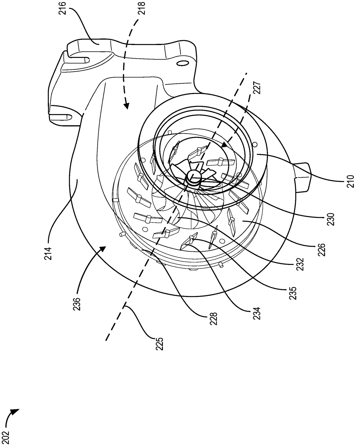
[0031] The following description relates to systems and methods for nozzle vane design of a variable nozzle turbine for a turbocharged engine. Such as figure 1 As shown, the variable nozzle turbine may be an exhaust driven turbine that generates power to operate a compressor coupled to the turbine via a shaft. In this way, the exhaust gas drives the turbine to supply energy to the compressor to boost the pressure and increase the air flow into the engine. Boost pressure may be controlled by a variable turbine rotational speed that is at least partially controlled by flow of exhaust gas through the turbine. Figure 2A to Figure 2B are shown similar to figure 1 A first and a second 3D view of a variable nozzle turbine of the turbine shown. A variable nozzle turbine may include an exhaust passage connected to exhaust outlets on the engine cylinders and a bypass passage directing the exhaust to an exhaust recovery system. Such as Figure 2A As shown, a turbine wheel having a ...


PUM

PropertyMeasurementUnit
Heightaaaaaaaaaa

Abstract

The invention relates to a nozzle blade design for a variable nozzle turbine. Systems are provided for a nozzle blade for a variable nozzle turbine of a turbocharged engine. In one example, a nozzle blade for a turbine nozzle of a variable geometry turbine may include: a cambered outer surface that curves from an inlet end to an outlet end of the nozzle blade, relative to a chord of the nozzle blade, the chord having a chord length defined from the inlet end to the outlet end, the nozzle blade having an aspect ratio in a range of 1.54 to 2.95, a thickness that is greatest in a range of 47 to 61% of the chord length, and a camber line angle change ratio in a range of 0.94 to 1.16 from the inlet end to the outlet end of the nozzle blade.

Description

technical field [0001] The present invention generally relates to methods and systems for nozzle vanes of variable nozzle turbines for turbocharged engines. Background technique [0002] Turbochargers may be provided in engines to improve engine torque or power output density. A turbocharger may include an exhaust-driven turbine coupled to a compressor via a drive shaft. A compressor may be fluidly coupled to an air intake manifold in the engine. Exhaust flow from one or more engine cylinders may be directed to an impeller in the turbine, causing the turbine to rotate about a fixed axis. The rotational motion of the turbine drives a compressor that compresses air into the air intake manifold to improve boost pressure based on engine operating conditions. Variable nozzle turbines may be used in turbochargers to control engine boost pressure by varying the exhaust flow conditions at the turbine nozzle. In this case, the geometry of the variable nozzle turbine can be varied...

Claims


Application Information

Patent Timeline
IPC IPC(8): F01D17/16F01D9/04F02B37/24
CPCF01D9/041F01D17/165F02B37/24F05D2220/40F01D17/16F01D5/04F05D2240/128F05D2240/80
Inventor 胡良军易建文
Owner FORD GLOBAL TECH LLC
Learn More