Ultrasonic device and ultrasonic sensor

Pending Publication Date: 2021-07-22
SEIKO EPSON CORP
View PDF0 Cites 0 Cited by
  • Summary
  • Abstract
  • Description
  • Claims
  • Application Information

AI Technical Summary

Benefits of technology

The technical effect of this patent is to prevent the accuracy of ultrasonic devices from decreasing.

Problems solved by technology

However, in the ultrasonic device including the substrate and the vibration plate having the vibrators in the related art, a formation portion or the like of the vibrators may vibrate due to crosstalk accompanying with vibration of the vibrators, and for example, vibration of a reception element or the like among the vibrators may be affected by the crosstalk and reception accuracy may be lowered.

Method used


Image

  • Ultrasonic device and ultrasonic sensor
  • Ultrasonic device and ultrasonic sensor
  • Ultrasonic device and ultrasonic sensor

Examples


first embodiment

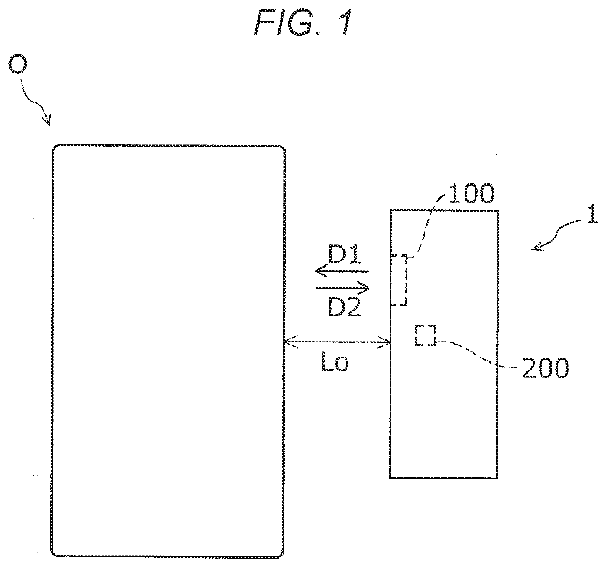
[0041]First, an ultrasonic sensor 1 according to a first embodiment, serving as an example of an ultrasonic device according to the present disclosure, will be described with reference to FIGS. 1 to 9.

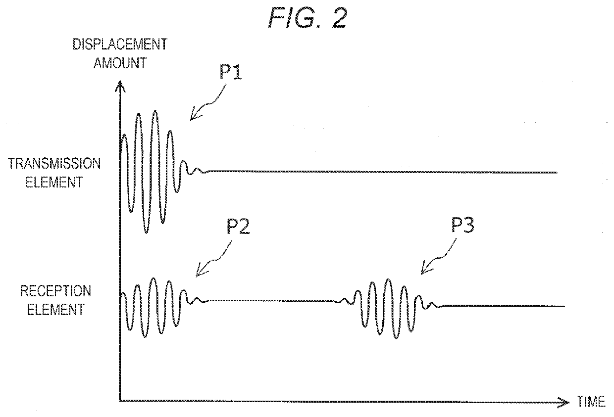
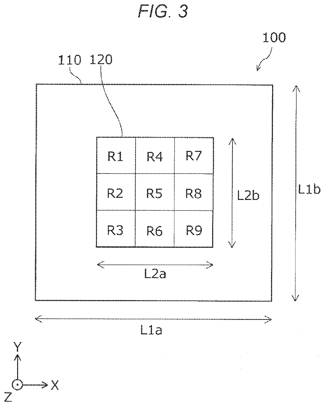
[0042]As shown in FIG. 1, the ultrasonic sensor 1 includes a transmission and reception unit 100 that transmits ultrasonic waves in a transmission direction D1 and receives ultrasonic waves that are reflected by an object O and move in a reception direction D2. As will be described later in detail, the transmission and reception unit 100 includes a transmission element 124a that transmits ultrasonic waves and a reception element 124b that receives ultrasonic waves transmitted from the transmission element 124a as shown in FIG. 8.

[0043]The ultrasonic sensor 1 further includes a timer 200 that measures time up to reception of ultrasonic waves transmitted from the transmission and reception unit 100. The ultrasonic sensor 1 can measure a distance Lo from the ultrasonic sensor 1 to the obj...

second embodiment

[0076]Next, an ultrasonic sensor according to a second embodiment will be described with reference to FIG. 10. FIG. 10 corresponds to FIG. 8 showing the ultrasonic sensor 1 according to the first embodiment. In FIG. 10, components the same as those in the first embodiment will be denoted by the same reference numerals and detailed description thereof will be omitted. The ultrasonic sensor according to the present embodiment has the same characteristics as the ultrasonic sensor 1 according to the first embodiment described above, and has the same configuration as the ultrasonic sensor 1 according to the first embodiment except for the following points. Specifically, the ultrasonic sensor according to the present embodiment has the same configuration as the ultrasonic sensor 1 according to the first embodiment except a configuration of the transmission and reception unit 100.

[0077]As shown in FIG. 10, the transmission and reception unit 100 of the ultrasonic sensor according to the pr...

third embodiment

[0079]Next, an ultrasonic sensor according to a third embodiment will be described with reference to FIG. 11. FIG. 11 corresponds to FIG. 8 showing the ultrasonic sensor 1 according to the first embodiment. In FIG. 11, components the same as those in the first embodiment and the second embodiment will be denoted by the same reference numerals and detailed description thereof will be omitted. Here, the ultrasonic sensor according to the present embodiment has the same characteristic as the ultrasonic sensor 1 according to the above-described first embodiment and second embodiment, and has the same configuration as the ultrasonic sensor 1 according to the first embodiment and the second embodiment except for the following points. Specifically, the ultrasonic sensor according to the present embodiment has the same configuration as the ultrasonic sensor 1 according to the first embodiment and the second embodiment except a configuration of the transmission and reception unit 100.

[0080]A...


PUM


Abstract

Provided is an ultrasonic device including a substrate and a vibration plate provided on the substrate and having one or more vibrators configured to generate an ultrasonic wave by vibration. The vibration plate has a movable portion provided with the vibrator and configured to vibrate accompanying with the vibration of the vibrator, and a fixed portion fixed to the substrate. A vibration frequency of a reflected wave based on a wave transmitted from the movable portion and received by the movable portion is outside a vibration frequency band region of the vibrator.

Description

[0001]The present application is based on, and claims priority from JP Application Serial Number 2020-007660, filed Jan. 21, 2020, the disclosure of which is hereby incorporated by reference herein in its entirety.BACKGROUND1. Technical Field[0002]The present disclosure relates to an ultrasonic device and an ultrasonic sensor.2. Related Art[0003]The related art discloses an ultrasonic device including a substrate and a vibration plate having vibrators. An example of such an ultrasonic device includes an ultrasonic sensor disclosed in JP-A-2015-188202. The ultrasonic sensor includes a substrate on which openings are formed, a vibration plate provided on the substrate so as to close the openings, active portions each serving as a vibrator formed by overlapping a piezoelectric layer, a first electrode, and a second electrode, and a vibration prevention portion provided between the active portions.[0004]However, in the ultrasonic device including the substrate and the vibration plate ha...

Claims


Application Information

Patent Timeline
IPC IPC(8): B06B1/06
CPCB06B1/0622G01S15/02G01S15/10G01S7/521B06B1/0629
Inventor KOJIMA, CHIKARAOHASHI, KOJISAYAMA, TOMOHIROIZUO, SEIJIKIYOSE, KANECHIKA
Owner SEIKO EPSON CORP
Why Eureka
Try Eureka