Wireless base station apparatus, wireless terminal apparatus, frequency resource allocation method, and method of forming transmission signal

Active Publication Date: 2012-01-12
SUN PATENT TRUST
View PDF6 Cites 29 Cited by
  • Summary
  • Abstract
  • Description
  • Claims
  • Application Information

AI Technical Summary

Benefits of technology

[0026]According to the present invention, it is possible to provide a radio base station apparatus, a radio terminal apparatus, a method of assigning frequency resources, and a method of forming transmission signals for making it possible to prevent the accuracy of channel estimation from lowering when non-contiguous frequency transmission and SRS transmission are employed in an uplink channel.
[0027]FIG. 1 shows non-contiguous frequency transmission;
[0028]FI

Problems solved by technology

Generally, path loss for a signal that is transmitted from a terminal near the cell border and is received by a base station, is significant.
Further, because the maximum transmission power of a terminal is lim

Method used


Image

  • Wireless base station apparatus, wireless terminal apparatus, frequency resource allocation method, and method of forming transmission signal
  • Wireless base station apparatus, wireless terminal apparatus, frequency resource allocation method, and method of forming transmission signal
  • Wireless base station apparatus, wireless terminal apparatus, frequency resource allocation method, and method of forming transmission signal

Examples


embodiment 1

[0044]FIG. 6 is a block diagram showing a configuration of a base station apparatus 100 according to Embodiment 1 of the present invention. In FIG. 6, base station apparatus 100 includes radio reception section 101, demodulation section 102, SRS extraction section 103, CQI estimation section 104, assignment section 105, assignment unit setting section 106, control signal generation section 107, modulation section 108, and radio transmission section 109.

[0045]Radio reception section 101 performs reception processing, such as down-conversion and A / D conversion, on a signal received from terminal apparatus 200 (described later) via an antenna, and outputs the reception-processed signal to demodulation section 102.

[0046]Demodulation section 102 demodulates the signal received from radio reception section 101 and outputs the demodulated signal to SRS extraction section 103.

[0047]SRS extraction section 103 extracts an SRS transmitted from terminal apparatus 200 based on SRS information re...

embodiment 2

[0096]A case has been described with Embodiment 1 where the basic size of an RBG is determined by setting the sounding band as the standard, and an end of the RBG is made match an end of the sounding band. A case will be described with Embodiment 2 where by setting the basic size and the position of an RBG as the standard, the transmission bandwidth with which terminal apparatus 200 transmits an SRS at one timing is determined, and an end of the transmission band of that SRS is made match an end of an RBG.

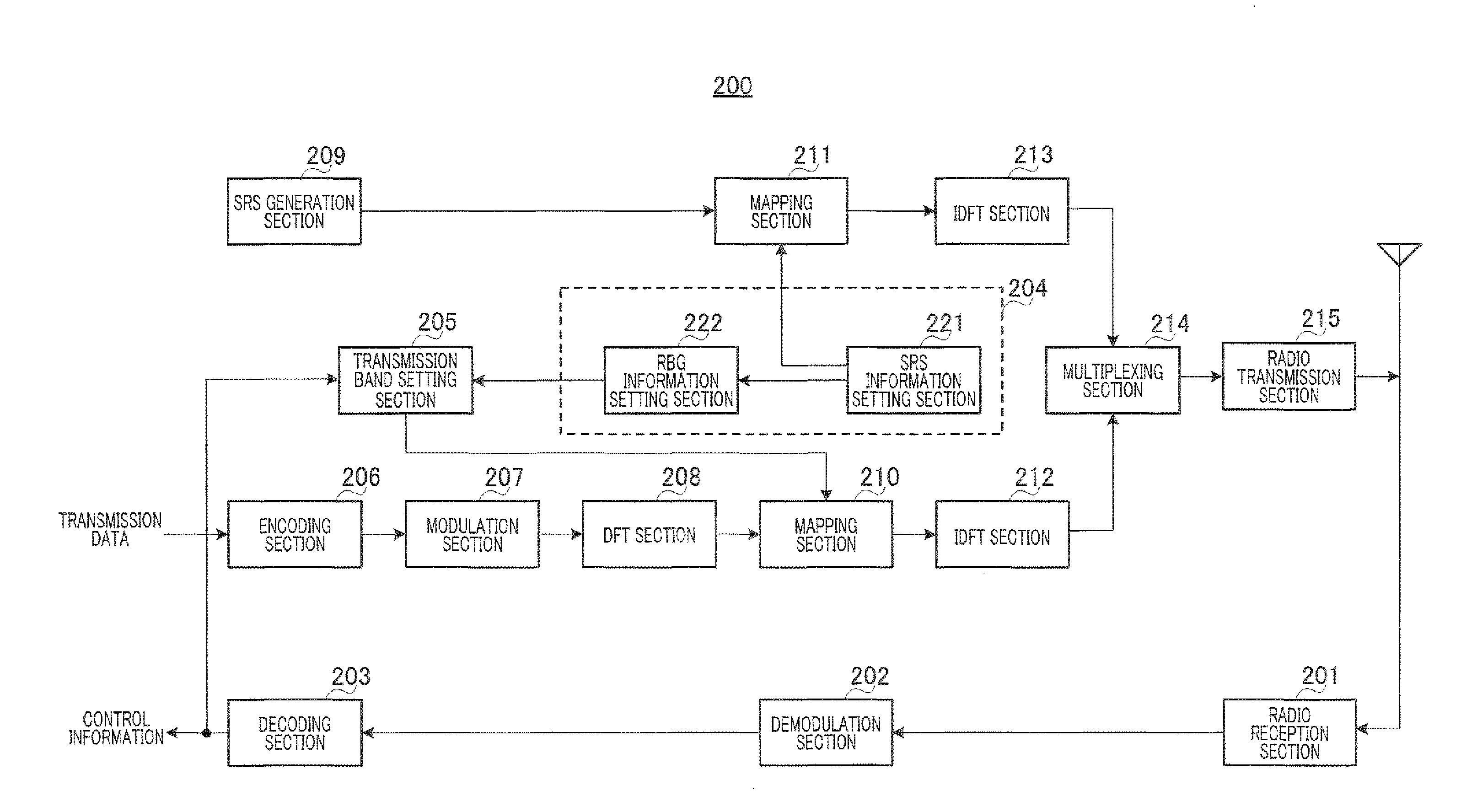
[0097]FIG. 14 is a block diagram showing a configuration of base station apparatus 300 according to Embodiment 2 of the present invention. Base station apparatus 300 includes assignment unit setting section 301.

[0098]Assignment unit setting section 301 outputs SRS information containing information about the transmission bandwidth, the position of the transmission band, and the frequency hopping pattern with which terminal apparatus 400 (described later) transmits an SRS at one tim...


PUM


Abstract

A wireless base station apparatus and wireless terminal apparatus with a configuration which can prevent reductions in the accuracy of channel estimation when non-contiguous band transmission and SRS transmission are employed in an uplink line. In the base station apparatus (100), an allocation setting unit (106), which sets the reception band of an SRS at an SRS extraction unit (103) and sets the units of frequency allocation (RBG) at a CQI estimation unit (104) and allocation unit (105), matches the frequency position at the end of the SRS reception band to the frequency position at the end of any of the units of frequency allocation and sets the reception bandwidth of the reference signal to a natural number multiple of the bandwidth of the unit of frequency allocation. In the terminal apparatus (200), a band information setting unit (204), which sets the transmission band and units of frequency allocation (RBG), matches the frequency position at the end of the transmission band to the frequency position at the end of any of the units of frequency allocation and sets the transmission bandwidth of the SRS to a natural number multiple of the bandwidth of the unit of frequency allocation.

Description

TECHNICAL FIELD[0001]The present invention relates to a radio base station apparatus, a radio terminal apparatus, a method of assigning frequency resources, and a method of forming transmission signals.BACKGROUND ART[0002]For an uplink channel of LTE-A (LTE-Advanced), which is an evolved version of 3rd generation partnership project long-term evolution (3GPP LTE), using “non-contiguous frequency transmission” in addition to contiguous frequency transmission is under consideration to improve sector throughput performance (see Non-Patent Literature 1).[0003]Non-contiguous frequency transmission is a method of transmitting a data signal and a reference signal by assigning such signals to non-contiguous frequency bands, which are dispersed in a wide range of band. As shown in FIG. 1, in non-contiguous frequency transmission, it is possible to assign a data signal and a reference signal to discrete frequency bands. Therefore, in non-contiguous frequency transmission, compared to contiguo...

Claims


Application Information

Patent Timeline
IPC IPC(8): H04W72/04
CPCH04B1/713H04L5/0041H04L5/0048H04L5/0057H04W72/085H04L5/0064H04W24/00H04W72/0453H04L5/006H04W72/542H04W72/23H04W72/52H04W88/08H04L25/0224
Inventor IWAI, TAKASHINISHIO, AKIHIKOIMAMURA, DAICHINAKAO, SEIGOOGAWA, YOSHIHIKO
Owner SUN PATENT TRUST
Why Eureka
Try Eureka