Exposure apparatus

a technology of exposure apparatus and piping, which is applied in the field of exposure apparatus, can solve the problems of insufficient vibration separation between the holding member and the body, the difficulty of improving the overlay accuracy, and the inability to effectively suppress the propagation of vibration from the outside to the first member via the piping for relay, so as to prevent the vibration from degrading and prevent the effect of vibration

Active Publication Date: 2009-04-02
NIKON CORP
View PDF20 Cites 27 Cited by
  • Summary
  • Abstract
  • Description
  • Claims
  • Application Information

AI Technical Summary

Benefits of technology

[0010]With this apparatus, the coil section of the generator is mounted on the first member on which a member that is subject to electric power supply is arranged, and the drive section that drives the magnet section of the generator is mounted on the second member that is separated from the first member in terms of vibration, and also the magnet section faces the coil section via a predetermined clearance. Therefore, by generating electric power by electromagnetic induction at the coil section by driving the magnet section using the drive section, the electric power can be supplied to a member subject to electric power supply without propagating vibration from the outside to the first member. With this operation, it becomes possible to prevent vibration accompanying the electric power supply such as floor vibration from being propagated, and hence it becomes possible to prevent exposure accuracy from degrading due to the vibration.
[0012]With this apparatus, the first section that transmits and / or receives an electromagnetic wave is mounted on the first member on which a member that is subject to transmission / reception of an electric signal is arranged, and the second section that receives and / or transmits the electromagnetic wave from / to the first section is mounted on the second member that is separated from the first member in terms of vibration. Therefore, in a state of preventing propagation of vibration from the outside to the first member, transmission / reception of the signal can be performed between the member subject to transmission / reception of the electric signal on the first member and an external member. With this operation, it becomes possible to prevent vibration accompanying the signal transmission / reception such as floor vibration from being propagated, and hence it becomes possible to prevent exposure accuracy from degrading due to the vibration.
[0013]According to a third aspect of the present invention, there is provided a third exposure apparatus that exposes an object with an energy beam and forms a pattern on the object, the apparatus comprising: a first relay member to which one end of a piping for relay is connected; a second relay member to which the other end of the piping is connected; a first member on which the first relay member is mounted; a second member which is separated from the first member in terms of vibration and on which the second relay member is mounted; and a drive device that drives the second relay member at least in a vertical direction so that relative positions between the first relay member and the second relay member are maintained.
[0014]With this apparatus, the first relay member to which one end of a piping for relay is connected is mounted on the first member, and the second relay member to which the other end of the piping for relay is connected is mounted on the second member that is separated from the first member in terms of vibration, and the drive device drives the second relay member at least in a vertical direction so that the relative positions between the first relay member and the second relay member are maintained. Therefore, propagation of the vibration from the outside to the first member via the piping for relay can be effectively suppressed. With this operation, it becomes possible to suppress propagation of vibration caused by existence of the piping such as floor vibration, and hence it becomes possible to prevent exposure accuracy from degrading due to the vibration.

Problems solved by technology

However, even if the synchronous accuracy between the mask stage and the substrate stage is favorable, it is difficult to improve the overlay accuracy when vibration is propagated from the outside to a projection optical system.
In this manner, in an exposure apparatus, the holding member that holds a projection optical system and a body that is installed on a floor surface are separated in terms of vibration using a vibration isolation device or the like, but recently the vibration-wise separation of the holding member and the body as is described above has been no longer sufficient, due to finer patterns accompanying higher-integration of semiconductor devices.
That is, even if the holding member and the body are separated, as long as wiring for electric power supply or for signal transmission, or piping for coolant supply or the like exists between the holding member and the body, fine vibration from the floor surface is propagated to the projection optical system through the wiring or the piping, and even such fine vibration cannot be ignored now.

Method used


Image

  • Exposure apparatus
  • Exposure apparatus
  • Exposure apparatus

Examples


first embodiment

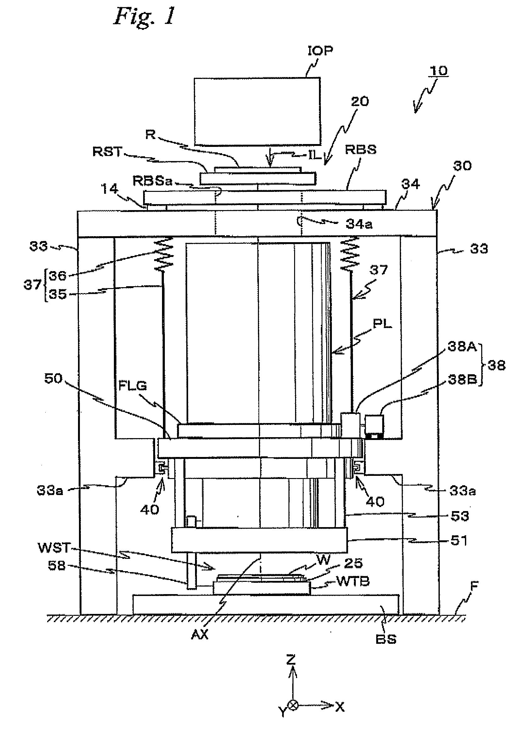
[0021]A first embodiment of the present invention will be described below, with reference to FIGS. 1 and 2.

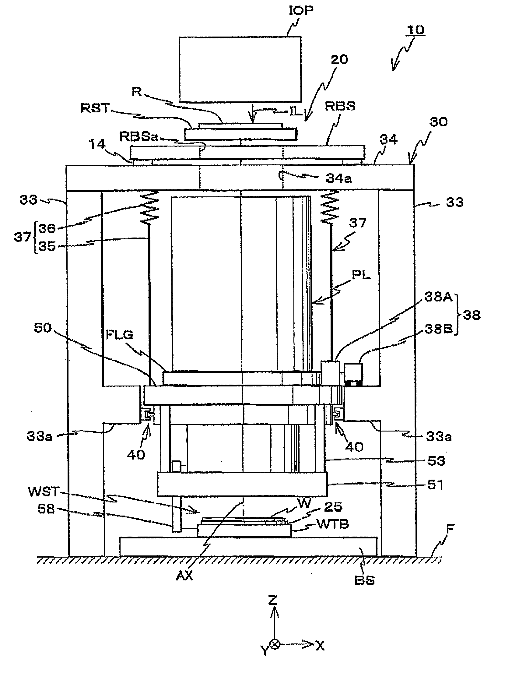
[0022]FIG. 1 shows a schematic configuration of an exposure apparatus 10 related to the first embodiment. Exposure apparatus 10 is a projection exposure apparatus by a step-and-scan method, which is a so-called scanner. As will be described later, a projection optical system PL is arranged in the embodiment, and the following explanation will be given assuming that a direction parallel to an optical axis AX of projection optical system PL is a Z-axis direction, a direction in which a reticle and a wafer are relatively scanned within a plane orthogonal to the Z-axis direction is a Y-axis direction, and a direction that is orthogonal to a Z-axis and a Y-axis is an X-axis direction, and rotation (tilt), directions about an X-axis, the Y-axis and the Z-axis are θx, θy and θz directions respectively.

[0023]Exposure apparatus 10 is equipped with an illumination unit IOP, a reticle sta...

second embodiment

[0054]Next, a second embodiment of the present invention will be explained. An exposure apparatus related to the second embodiment has an entire configuration similar to that of the first embodiment described above, but is different from the first embodiment in a point that instead of generator 38r an optical communication mechanism 70 shown FIG. 3 that transmits / receives signals (information) by optical communication is separately placed between barrel platform 50 and protruding section 33a of column 30. Accordingly, optical communication mechanism 70 will be described below.

[0055]Optical communication mechanism 70 is equipped with a first optical communication unit 71 fixed on barrel platform 50, and a second optical communication unit 72 mounted on protruding section 33a via a self-weight support mechanism (not shown) and a plurality of, for example, four voice coil motors 75 (the voice coil motors in the depth of the page surface are not shown in FIG. 3) so as to face first opti...

third embodiment

[0068]Next, a third embodiment of the present invention will be explained. An exposure apparatus related to the third embodiment has an entire configuration similar to that of the first embodiment described above, but is different from the first embodiment in a point that instead of generator 38, a piping relay mechanism 80 shown in FIG. 5 is separately placed between barrel platform 50 and protruding section 33a of column 30. Accordingly, piping relay mechanism 80 will be described below.

[0069]Piping relay mechanism 80 is equipped with a first piping unit 81 fixed on barrel platform 50, and a second piping unit 82 mounted on protruding section 33a via a self-weight support mechanism (not shown) and a plurality of, for example, four voice coil motors 84 (the voice coil motors in the depth of the page surface are not shown in FIG. 5). First piping unit 81 has a housing22 inside of which a manifold path is arranged. One end of a piping for relay 83 is connected to first piping unit 81...


PUM


Abstract

Electric power is generated by using a generator equipped with: a coil unit that is arranged on a barrel platform and incorporates coils; and a magnet unit that has a magnet section arranged on a protruding section of a column separated from the barrel platform in terms of vibration and generates an electromotive force in a non-contact state with the coils, and a motor that drives the magnet section, and thus a wiring that supplies electric power to the barrel platform does not have to be used. Accordingly, vibration that has been propagated to the barrel platform through the wiring can be precluded.

Description

CROSS-REFERENCE TO RELATED APPLICATIONS[0001]This non-provisional application claims the benefit of Provisional Application No. 60 / 960,374 filed Sep. 27, 2007, the disclosure of which is hereby incorporated herein by reference in its entirety.BACKGROUND OF THE INVENTION[0002]1. Field of the Invention[0003]The present invention relates to exposure apparatuses, and more particularly to an exposure apparatus that exposes an object with an energy beam and forms a pattern on the object.[0004]2. Description of the Background Art[0005]In a lithography process on manufacturing electronic devices (microdevices) such as semiconductor devices and liquid crystal display devices, exposure apparatuses such as a projection exposure apparatus by a step-and-repeat method (a so-called stepper) or a projection exposure apparatus by a step-and-scan method (a so-called scanning stepper (which is also called a scanner) are relatively frequently used.[0006]Meanwhile, because a semiconductor device or the ...

Claims


Application Information

Patent Timeline
Patent Type & Authority Applications(United States)
IPC IPC(8): G03B27/42
CPCG03F7/70883H02J5/005G03F7/70991G03F7/709H02J50/10
Inventor SHIBAZAKI, YUICHI
Owner NIKON CORP
Why Eureka
Try Eureka