
Systems and methods for monitoring tillage conditions

a technology of tillage conditions and monitoring systems, applied in the field of systems and methods for monitoring tillage conditions, can solve the problems of crop yield loss, crop skips, and tillage conditions such as the levelness of the tillage floor, and the like of the tillage layer may be impacted significantly,

Pending Publication Date: 2021-07-29
CNH IND CANADA
View PDF15 Cites 2 Cited by
  • Summary
  • Abstract
  • Description
  • Claims
  • Application Information

AI Technical Summary

Benefits of technology

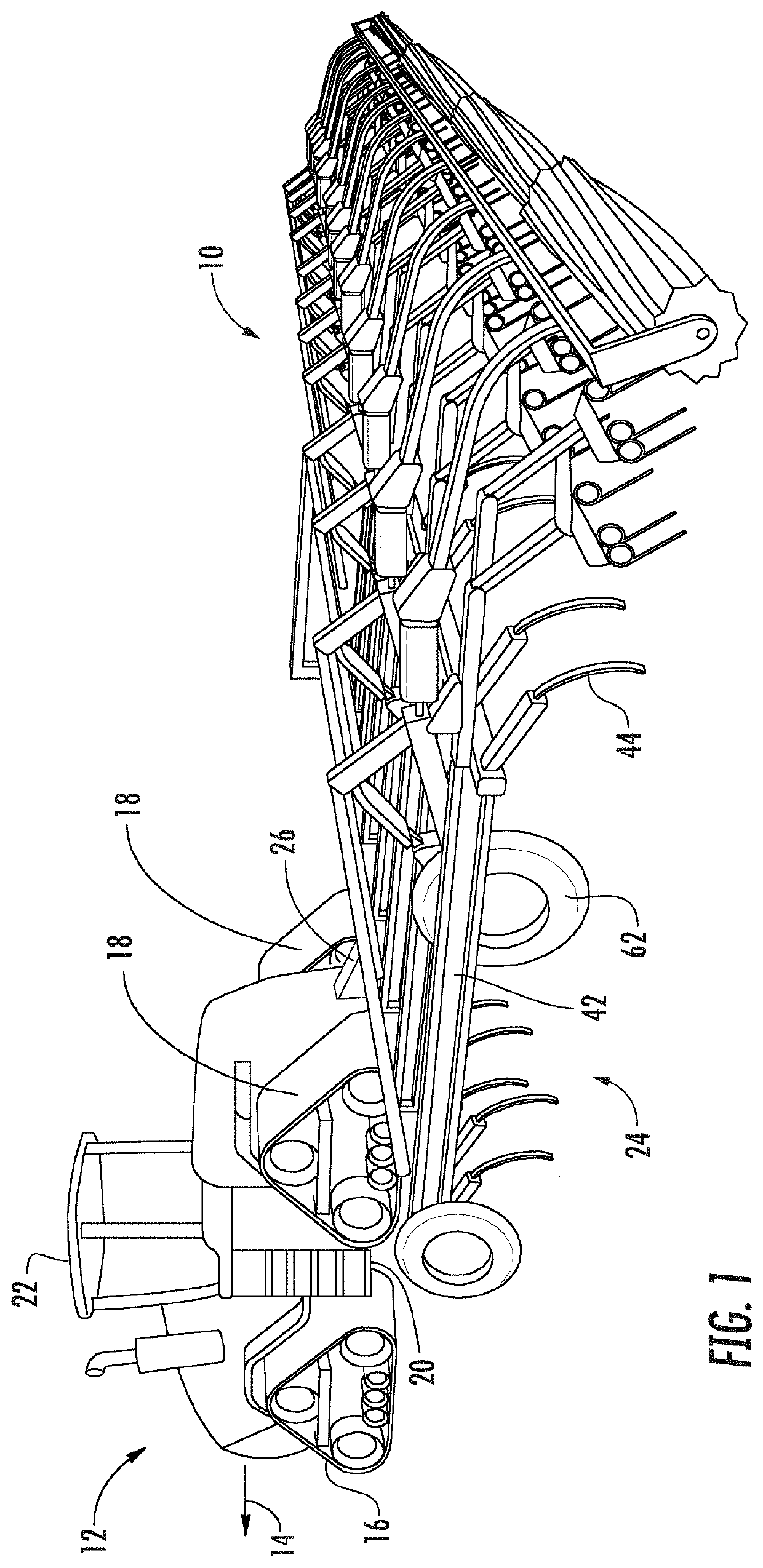
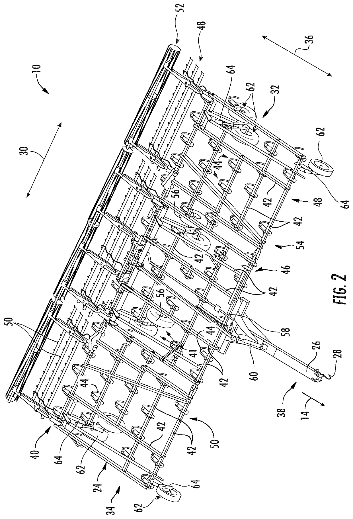
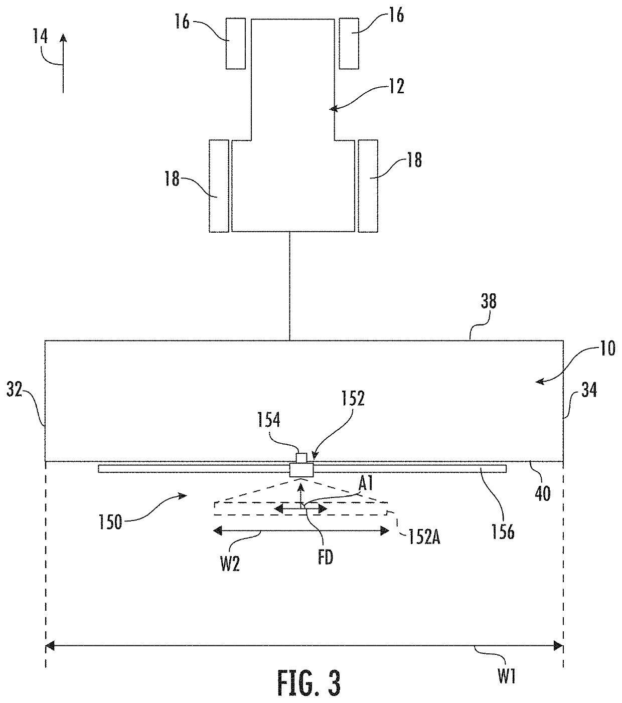
The present invention is about a system and method for monitoring the conditions of a field during tillage. The system includes an agricultural implement, a tillage sensor, and a controller. The tillage sensor is attached to the implement and has a field of view directed towards a portion of the field. The sensor generates data that indicates the levelness of the tillage floor, which is underneath the field surface. The controller receives this data and monitors the levels of the tillage floor as the implement moves across the field. The controller can also actuate the sensor to change its field of view, which allows for more accurate monitoring as the implement moves. The technical effect of this invention is to provide a way for farmers to monitor and fine-tune their tillage practices in real-time, which can improve soil quality and crop yields.

Problems solved by technology

However, due to varying soil conditions across the field, implement settings, and / or other factors, tillage conditions such as the levelness of the tillage floor, compaction, water content, and / or the like of the tillage layer may be impacted significantly.
Poor tillage conditions can result in losses in crop yield.
For example, poor tillage floor levelness may cause seed skips during the planting operation.

Method used


Image

  • Systems and methods for monitoring tillage conditions
  • Systems and methods for monitoring tillage conditions
  • Systems and methods for monitoring tillage conditions

Examples


Embodiment Construction

[0024]Reference now will be made in detail to embodiments of the invention, one or more examples of which are illustrated in the drawings. Each example is provided by way of explanation of the invention, not limitation of the invention. In fact, it will be apparent to those skilled in the art that various modifications and variations can be made in the present invention without departing from the scope or spirit of the invention. For instance, features illustrated or described as part of one embodiment can be used with another embodiment to yield a still further embodiment. Thus, it is intended that the present invention covers such modifications and variations as come within the scope of the appended claims and their equivalents.

[0025]In general, the present subject matter is directed to systems and methods for monitoring tillage conditions of a field as an agricultural implement moves across the field. Specifically, in accordance with aspects of the present subject matter, the dis...


PUM


Abstract

A system for monitoring tillage conditions of a field may include an agricultural implement and a tillage sensor supported on the agricultural implement. The tillage sensor has a field of view directed towards a portion of the field disposed relative to the agricultural implement, with the tillage sensor being configured to generate data indicative of a tillage floor levelness associated with a tillage floor of the field disposed below a surface of the field. The system may further include a controller configured to receive the data from the tillage sensor indicative of the tillage floor levelness as the agricultural implement moves across the field and monitor the tillage floor levelness based at least in part on the data received from the tillage sensor.

Description

FIELD OF THE INVENTION[0001]The present disclosure relates generally to systems and methods for monitoring tillage conditions and, more particularly, to systems for monitoring tillage conditions as an agricultural implement moves across a field.BACKGROUND OF THE INVENTION[0002]It is well known that, to attain the best agricultural performance from a field, a farmer must cultivate the soil, typically through a tillage operation. Tillage implements typically include a plurality of ground engaging tools configured to engage the soil as the implement is moved across the field. Such ground engaging tool(s) loosen and / or otherwise agitate the soil up to a certain depth in the field to prepare the field for subsequent agricultural operations, such as planting operations.[0003]When performing a tillage operation, it is desirable to create a level and uniform layer of tilled soil across the field to form a proper seedbed in subsequent planting operations. However, due to varying soil conditi...

Claims


Application Information

Patent Timeline
IPC IPC(8): A01B63/28A01B79/00A01B49/02
CPCA01B63/28A01B49/027A01B79/005A01B47/00A01B63/1112
Inventor HENRY, JAMES W.WHITTOME, SAMUEL EDMUNDKIMPTON, LAURA SARANNEJONES, ROSS PETER
Owner CNH IND CANADA
Learn More