
Conductive member and image forming apparatus

Pending Publication Date: 2021-07-29
CANON KK
View PDF2 Cites 0 Cited by
  • Summary
  • Abstract
  • Description
  • Claims
  • Application Information

AI Technical Summary

Benefits of technology

The present invention aims to provide a conductive member that can be easily arranged, is cost-effective, and has reliable electrical conduction.

Problems solved by technology

Therefore, grounding cannot be performed by the method of the related art.
Provision of an additional metal plate to the image forming apparatus for the purpose of grounding causes the increases in the number of assembly steps and a cost for the image forming apparatus.
However, when the plate spring is used as the relay member, a degree of freedom in molding and a degree of freedom in arrangement may become lower, and a length of the relay member may become larger.
As a result, there is a fear in that the apparatus is increased in size and cost.
As a result, there is a fear in that reliable electrical conduction is impaired.

Method used


Image

  • Conductive member and image forming apparatus
  • Conductive member and image forming apparatus
  • Conductive member and image forming apparatus

Examples


embodiments

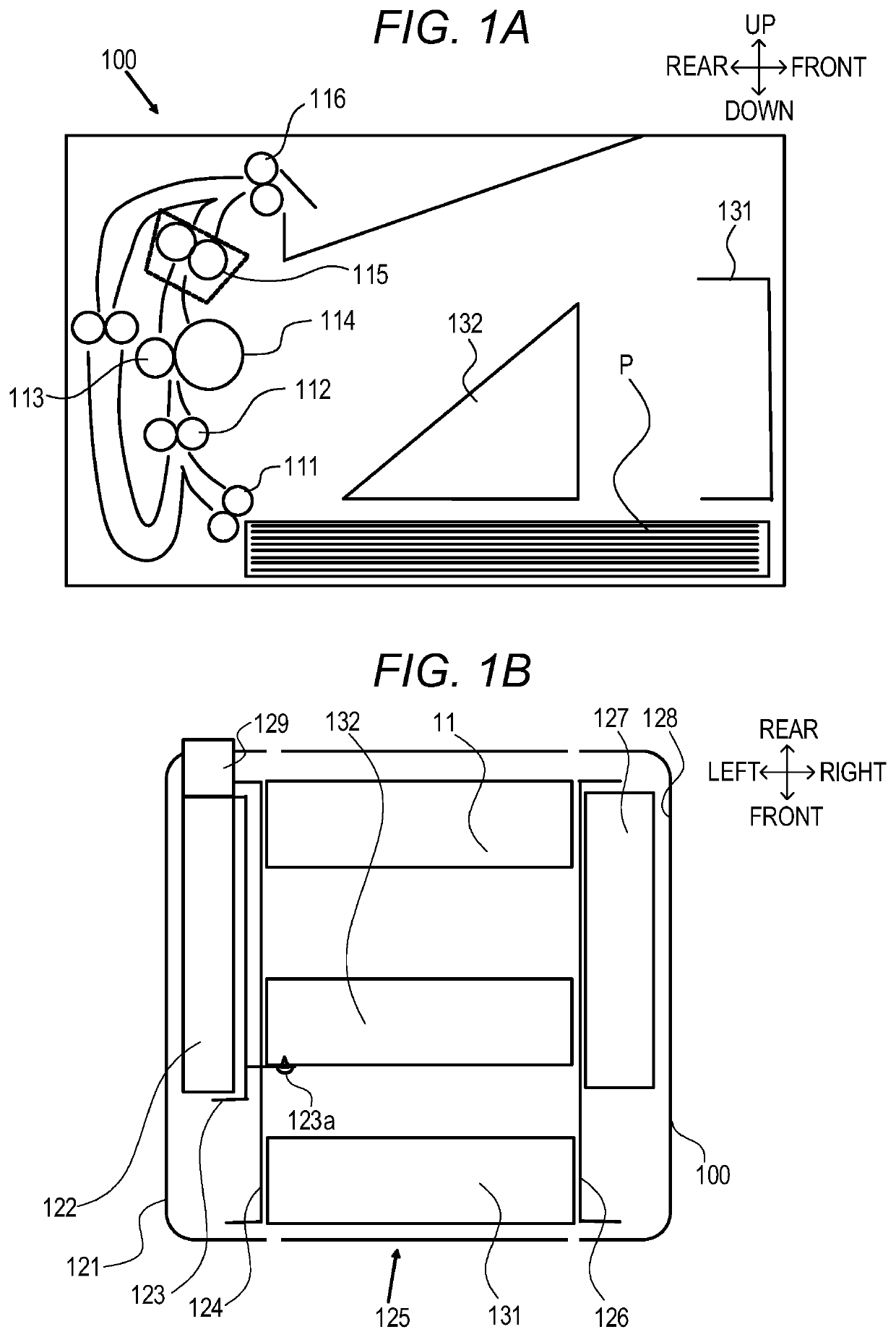
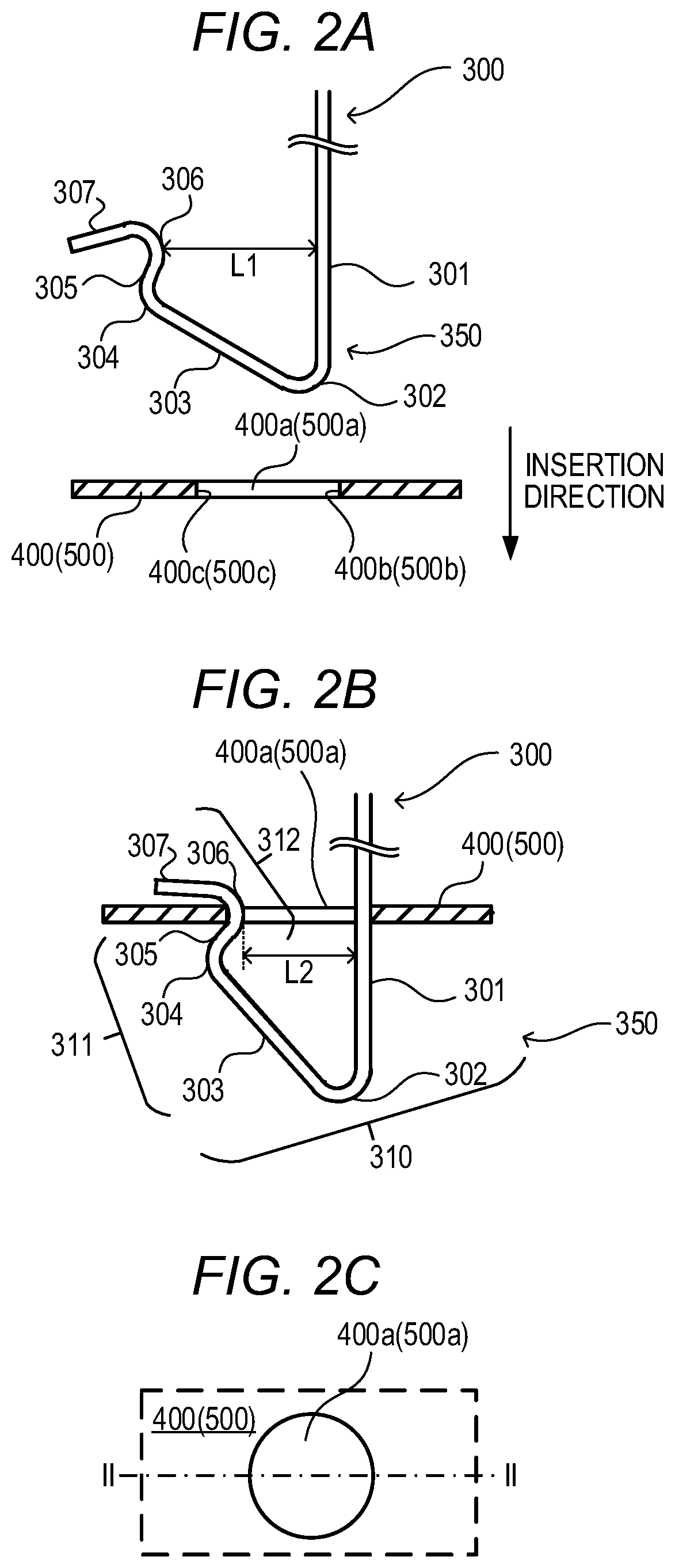
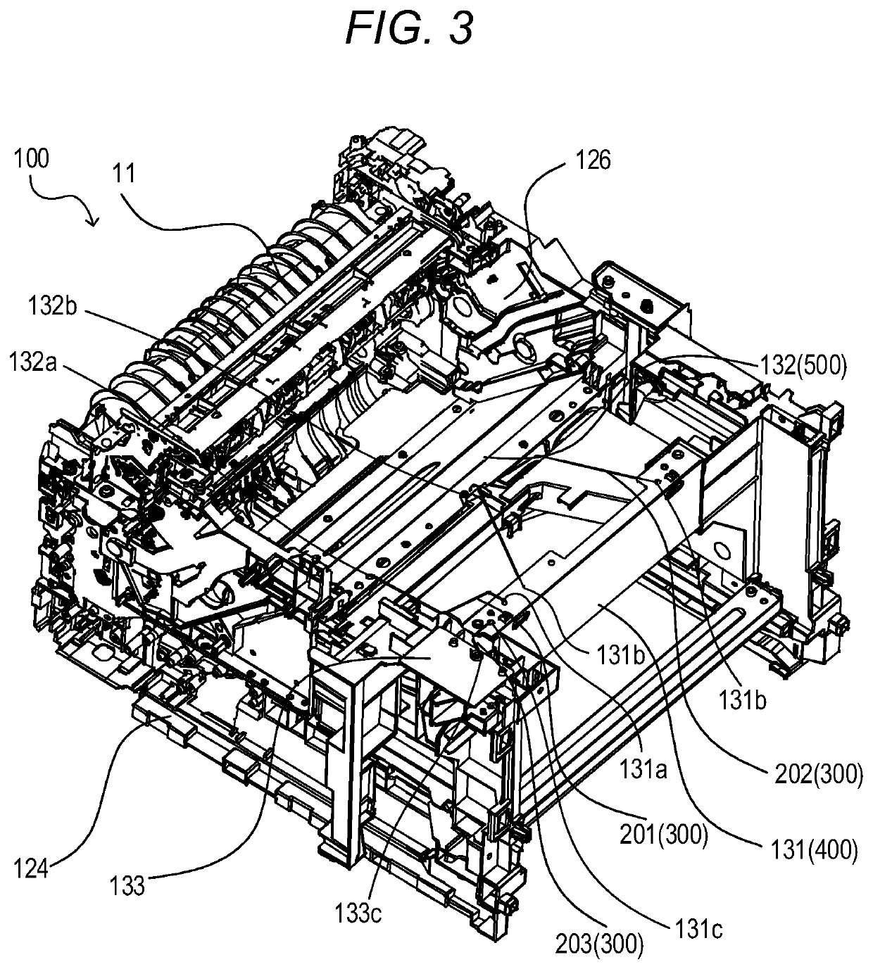
[0030]A wire spring relay member 300 is descried as a conductive member according to the embodiments for electrically connecting a grounded member and an already grounded member, which is a metal plate member, and establishing a ground. FIG. 2A and FIG. 2B are views for illustrating a connection portion 350 that is a characteristic configuration of the wire spring relay member 300. FIG. 2A is an enlarged view for illustrating a main part before connection between the connection portion 350 of the wire spring relay member 300 and the grounded member 400 or the already grounded member 500. FIG. 2B is an enlarged view for illustrating the main part during the connection between the connection portion 350 of the wire spring relay member 300 and the grounded member 400 or the already grounded member 500. FIG. 2C is a top view of a through-hole 400a of the grounded member 400 or a through-hole 500a of the already grounded member 500. As illustrated in FIG. 2A, the grounded member 400 (alr...


PUM


Abstract

A conductive member includes a connection portion which is to be electrically connected to a cutaway portion of a metal plate. The connection portion includes a first arm portion extending from one end to another end and configured to come into contact with one face of two faces opposed to each other of the cutaway portion, a first bent portion connected to the another end of the first arm portion and bent extending from the another end toward the one end, a second bent portion connected to the first bent portion and bent getting closer toward the first arm portion as getting away from the first bent portion, and a third bent portion connected to the second bent portion and bent getting away from the first arm portion as getting away from the second bent portion so as to come into contact with another face of the two faces.

Description

BACKGROUND OF THE INVENTIONField of the Invention[0001]The present invention relates to a conductive member and an image forming apparatus.Description of the Related Art[0002]An image forming apparatus includes a variety of metal plates disposed therein, such as a frame for holding a light scanning apparatus. The metal plates themselves serve as antennas, and may emit noises generated inside and outside the image forming apparatus to an inside and an outside of the image forming apparatus. To prevent such noises and radio frequency interference (RFI), the meal plates inside the image forming apparatus need to be grounded. In related art, internal metal plates are fastened to a metal side plate of the image forming apparatus with screws and are grounded via the side plate.[0003]In recent years, from the perspective of downsizing and a high degree of freedom in molding, there has been a trend of forming the side plate of the image forming apparatus with plastic. Therefore, grounding c...

Claims


Application Information

Patent Timeline
IPC IPC(8): H04N1/00
CPCH04N1/00994H04N1/00557
Inventor YAMAMOTO, DAISUKE
Owner CANON KK
Learn More