
A rail connection block

A technology of connecting blocks and guide rails, applied in photovoltaic modules, supporting structures of photovoltaic modules, electrical components, etc., can solve the problems of inability to ensure electrical continuity, cumbersome operation, poor aesthetics, etc., to improve aesthetics and cleanliness, operation. The effect of convenient and reliable electrical conduction

Active Publication Date: 2019-02-05
胡阳
View PDF10 Cites 0 Cited by
  • Summary
  • Abstract
  • Description
  • Claims
  • Application Information

AI Technical Summary

Problems solved by technology

[0002] The guide rails currently on the market for installing solar panels are connected by locking, that is, the guide rails to be spliced ​​are spliced ​​and fastened together by means of bolts. The main inconveniences are: 1. Poor aesthetics , Due to the necessary movable space for disassembling and assembling bolts, most of the bolts are exposed outside the guide rail, and hidden installation cannot be realized; 2. The use of bolts requires a wrench to complete, and the operation is cumbersome and inefficient, and often brings a lot of inconvenience due to the wrench operating space; 3. The adjacent guide rails are fixed by locking. Due to the influence of the installation gap and the oxide layer of the guide rails or connecting blocks, reliable electrical conduction between components cannot be guaranteed, and the grounding requirements for solar panel installation cannot be fully met.

Method used


Image

  • A rail connection block
  • A rail connection block
  • A rail connection block

Examples


Embodiment

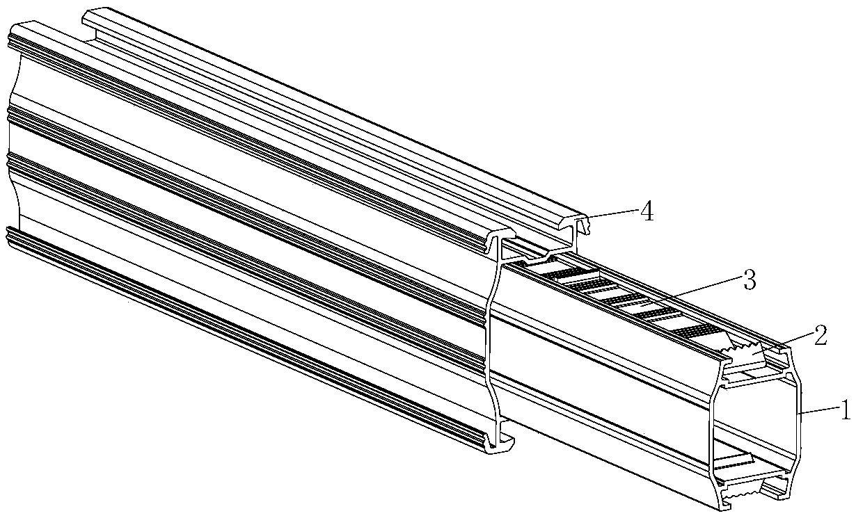
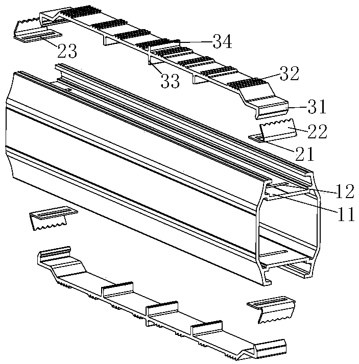
[0024] like figure 1 and figure 2 As shown, a guide rail connection block is used for connection between fixed guide rails of solar panels, and is composed of a body 1 , a clamping piece 2 and a clamping piece 3 .

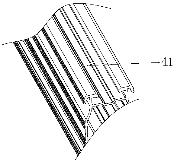
[0025] Wherein, the outer contour of the body 1 fits with the inner cavity of the guide rail 4 to be connected so as to be inserted into the inner cavity of the guide rail 4 . The upper end of the body 1 is provided with a longitudinal groove 11 consistent with the direction of the guide rail 4, and a button hole 12 is provided at the bottom of the groove at both ends of the longitudinal groove 11. In this embodiment, the shape of the button hole 12 is a square perpendicular to the longitudinal groove 11. Long holes.

[0026] There are two clamping pieces 2, which are symmetrically placed on the left and right sides of the longitudinal groove 11. The clamping piece 2 is a metal sheet with a straight section 21 and an upwardly folded section 22, and the hardness ...


PUM


Abstract

The invention discloses a guide rail connection block, which is used for connection between solar panel fixing guide rails. The guide rail connection block comprises a body, two clamping sheets and a clamping block, wherein the outer contour of the body is matched with an inner cavity of a guide rail which the body is connected to, so that the body is inserted in the guide rail; a longitudinal groove consistent with the guide rail in direction is formed in the upper end of the body; a fastener hole is formed in the groove bottom at each end of the longitudinal groove; the two clamping sheets are symmetrically arranged on the left and right sides of the longitudinal groove; the clamping sheets are metal sheets with straight sections and upwards turned sections; the hardness of the clamping sheets is greater than that of the guide rail; the straight sections of the clamping sheets are provided with through holes larger than the fastener holes; the upper edges of the turned sections of the clamping sheets are machined to be sharp tooth-shaped; when the straight sections cling to the groove bottom of the longitudinal groove, the upper edges of the turned sections exceed the inner cavity surface of the guide rail; a clamping piece is long-strip-shaped; two ends of the clamping piece extend downwards to form fastener feet; the fastener feet penetrate through the through holes of the clamping sheets and then are fastened in the fastener holes of the longitudinal groove, so that the clamping sheets are fixed in the longitudinal groove.

Description

technical field [0001] The invention relates to the field of solar panel installation, in particular to a guide rail connection block. Background technique [0002] The guide rails currently on the market for installing solar panels are connected by locking, that is, the guide rails to be spliced ​​are spliced ​​and fastened together by means of bolts. The main inconveniences are: 1. Poor aesthetics , Due to the necessary movable space for disassembling and assembling bolts, most of the bolts are exposed outside the guide rail, and hidden installation cannot be realized; 2. The use of bolts requires a wrench to complete, and the operation is cumbersome and inefficient, and often brings a lot of inconvenience due to the wrench operating space; 3. The adjacent guide rails are fixed by locking. Due to the influence of the installation gap and the oxide layer of the guide rails or connecting blocks, reliable electrical conduction between components cannot be guaranteed, and the ...

Claims


Application Information

Patent Timeline
Patent Type & Authority Patents(China)
IPC IPC(8): H02S20/00H02S30/10
CPCH02S20/00H02S30/10Y02E10/50
Inventor 胡阳
Owner 胡阳
Learn More