Display screen turning apparatus
a technology of display screen and turning table, which is applied in the direction of electrical apparatus casing/cabinet/drawer, furniture parts, instruments, etc., can solve the problem that the receiving body cannot be stably placed on the rotation stand, and achieve the effect of stably supporting the display screen portion and high degree of freedom in the arrangement of the display screen portion
- Summary
- Abstract
- Description
- Claims
- Application Information
AI Technical Summary
Benefits of technology
Problems solved by technology
Method used
Image
Examples
first embodiment
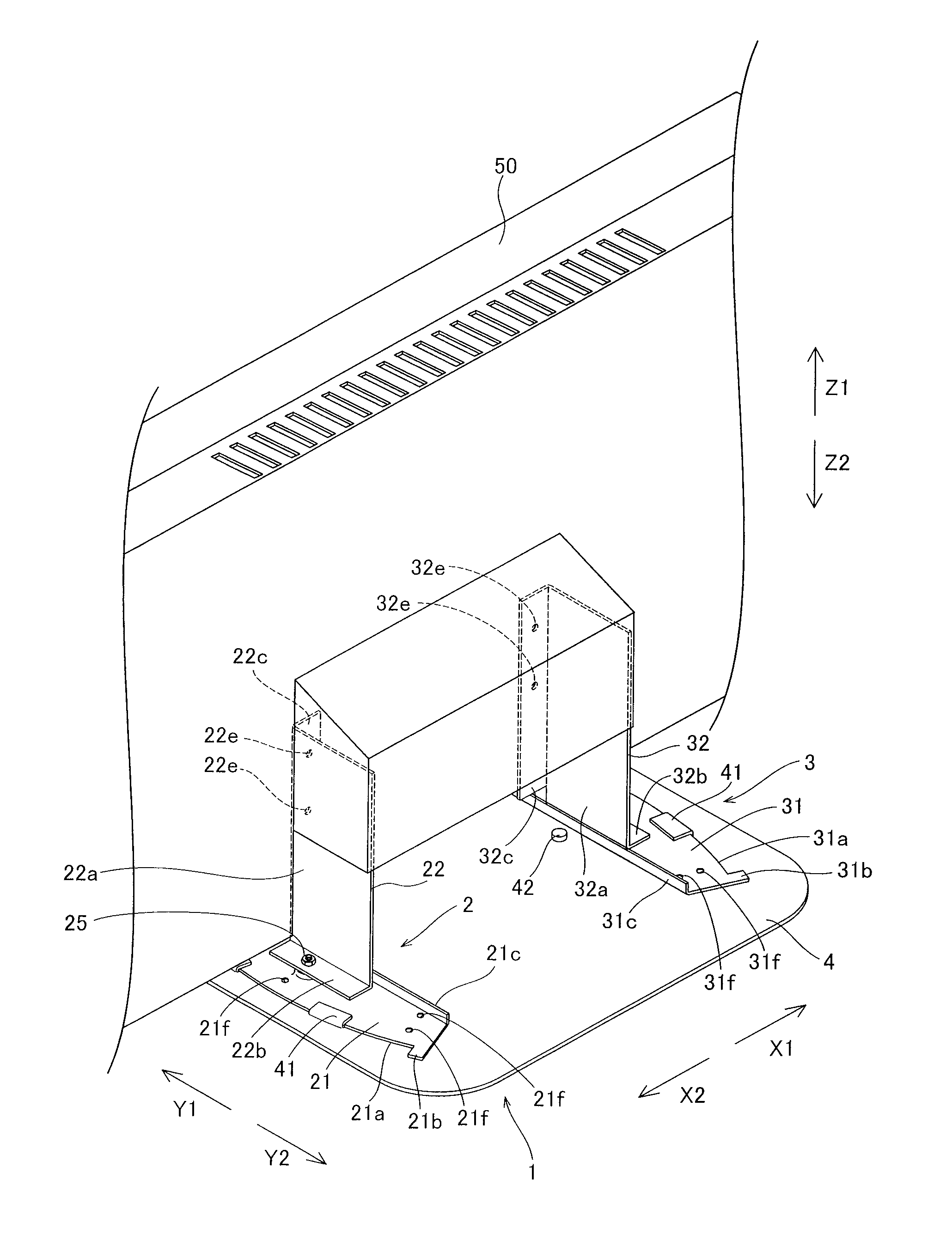
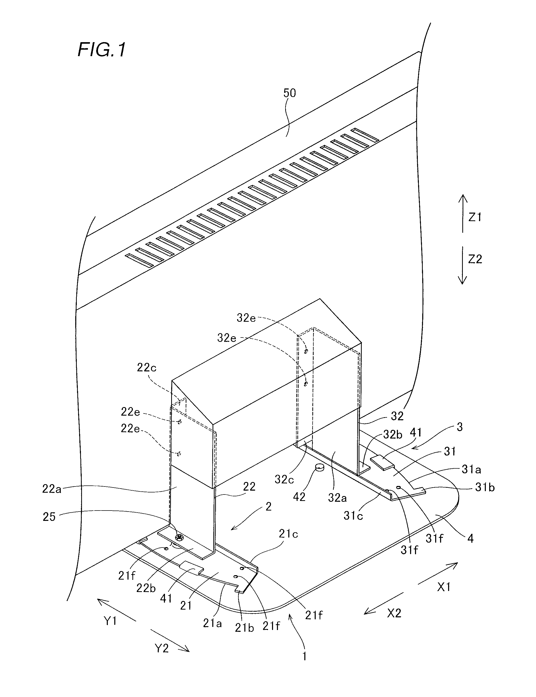
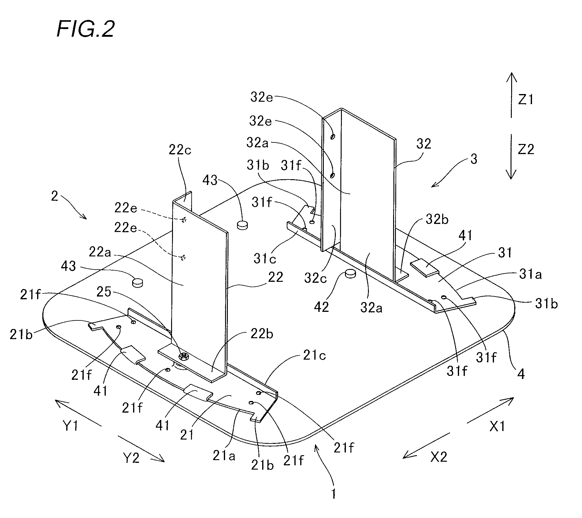
[0049]The structure of a display screen turning apparatus 1 according to a first embodiment of the present invention is described with reference to FIGS. 1 to 6.
[0050]The display screen turning apparatus 1 according to the first embodiment of the present invention includes a right rotation support portion 2, a left rotation support portion 3 and a base 4 of sheet metal, as shown in FIGS. 1 to 3. The right rotation support portion 2 is an example of the “first rotation support portion” in the present invention, and the left rotation support portion 3 is an example of the “second rotation support portion” in the present invention.
[0051]The right rotation support portion 2 is formed to support the right side (along arrow X2) of a display screen portion 50 as viewed from the front side and to rotate in the horizontal direction (along arrows A1 and A2) with respect to the base 4 independently of the left rotation support portion 3. More specifically, the right rotation support portion 2 ...
second embodiment
[0081]The structure of a display screen turning apparatus 100 according to a second embodiment of the present invention is now described with reference to FIGS. 11 to 15. According to the second embodiment, a display screen portion 50 can be rotated also in the anteroposterior direction in addition to the horizontal direction, dissimilarly to the aforementioned first embodiment.
[0082]The display screen turning apparatus 100 according to the second embodiment of the present invention includes a right rotation support portion 102, a left rotation support portion 103 and a base 4 of sheet metal, as shown in FIGS. 11 to 14. The right rotation support portion 102 is an example of the “first rotation support portion” in the present invention, and the left rotation support portion 103 is an example of the “second rotation support portion” in the present invention.
[0083]The right rotation support portion 102 is formed to support the right side (along arrow X2) of the display screen portion ...
PUM
 Abstract
Description
Claims
Application Information
 - R&D
- Intellectual Property
- Life Sciences
- Materials
- Tech Scout
- Unparalleled Data Quality
- Higher Quality Content
- 60% Fewer Hallucinations
Browse by: Latest US Patents, China's latest patents, Technical Efficacy Thesaurus, Application Domain, Technology Topic, Popular Technical Reports.
© 2025 PatSnap. All rights reserved.Legal|Privacy policy|Modern Slavery Act Transparency Statement|Sitemap|About US| Contact US: help@patsnap.com


