Lateral gripper
- Summary
- Abstract
- Description
- Claims
- Application Information
AI Technical Summary
Benefits of technology
Problems solved by technology
Method used
Image

Examples
Embodiment Construction
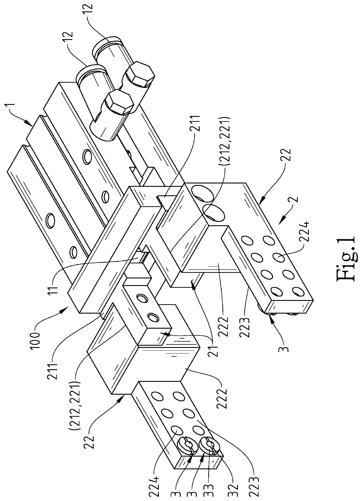
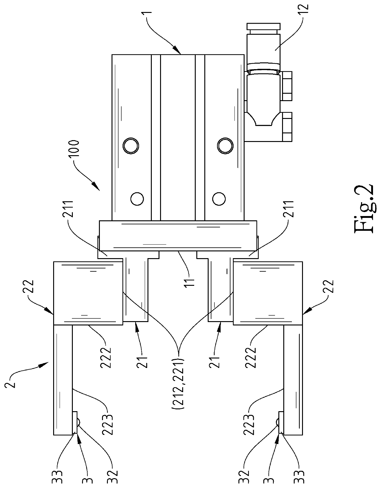
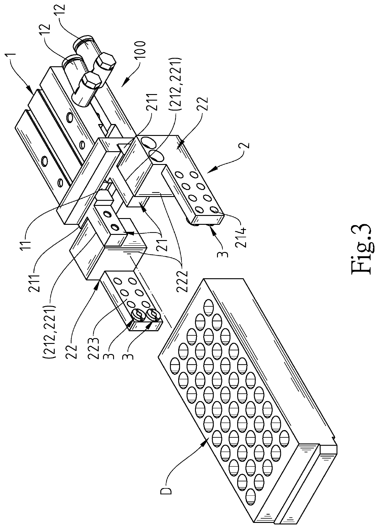
[0014]Referring to FIGS. 1-6, a lateral gripper 100 in accordance with a first embodiment of the present invention is shown. The lateral gripper 100 comprises a gripper mount 1 and two gripper jaw modules 2.
[0015]As shown in FIGS. 1-5, the gripper mount 1 is used for the mounting of the two gripper jaw modules 2. The gripper mount 1 comprises a transversely arranged linear sliding groove 11, and a connection unit 12 that has one end thereof connected to a driving device (not shown), and an opposite end thereof connected to the gripper jaw modules 2, so that the driving device can drive the gripper jaw modules 2 to move relative to each other. The driving device can be a hydraulic drive or a pneumatic drive. The driving principle of air pressure or hydraulic fluid pressure is not the scope of the claims of the present invention, so we won't go into details here.
[0016]As shown in FIGS. 1-6, the gripper jaw modules 2 are coupled to the linear sliding groove 11 and driven by the driving...
PUM
 Abstract
Description
Claims
Application Information