Al technical title is built by PatSnap Al team. It summarizes the technical point description of the patent document.
a protective case and mobile device technology, applied in the direction of electrical equipment, transmission, etc., can solve the problems of cracked screen, scratches on the finished surface, and damage to mobile devices such as smartphones, tablets, laptops,
Inactive Publication Date: 2021-08-26
VINCI BRANDS LLC
View PDF0 Cites 0 Cited by
Summary
Abstract
Description
Claims
Application Information
AI Technical Summary
This helps you quickly interpret patents by identifying the three key elements:
Problems solved by technology
Method used
Benefits of technology
Benefits of technology
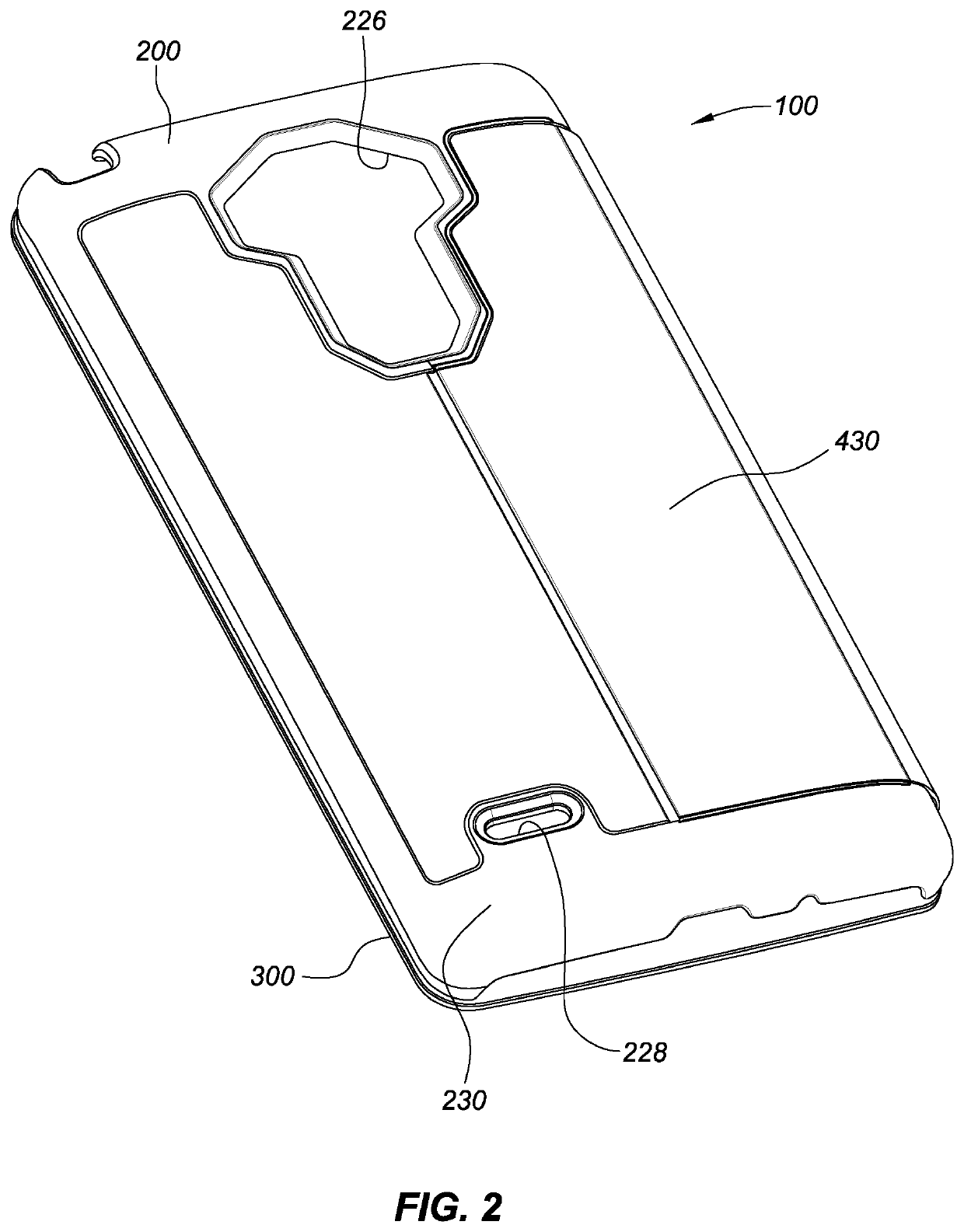
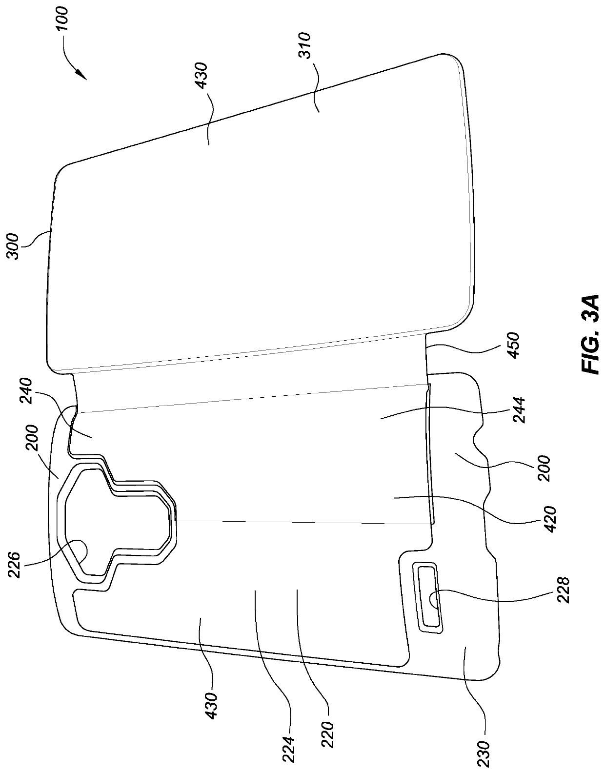
[0007]The shell may be comprised of a main panel and a detachable subpanel, each of which has corresponding inner and outer faces. The main panel defines the compartment and includes an aperture that is dimensioned to receive the subpanel. The subpanel is hinged along a first side or location within the aperture formed in the main panel and anchored on a second side to the cover via the spine. One or more attachment protrusions are provided and configured to mechanically engage, latch or clip the subpanel into the aperture of the main panel at or near the second side or location to thereby secure the subpanel to the main panel of the shell.
[0008]When the subpanel is attached or otherwise secured at the second location, the subpanel and main panel maintain a fixed relative position and orientation to one another. The subpanel is dimensioned such that when it is positioned within the aperture of the main panel, there is a slot or gap between opposing edges of the subpanel and the adjacent edge of the aperture. The aperture also includes indentation or a lip at one or more regions along its defining wall borders that is dimensioned to engage with the corresponding edge or lip regions of the subpanel so as to serve to stop the subpanel from swinging into the mobile device compartment formed by the shell and its main panel.
[0012]The inner and outer layers are generally configured to overlay the mid-regions of opposing sides of the main and subpanel panel and the cover panel and form a flexible spine between the cover and shell as well as to form the hinge between the sub-panel and main panel. Recessed attachment regions may be provided in the shell component panels so that the outer surfaces of the attached layers reside at or below the height of the adjacent regions of the shell panels. Such a configuration can mitigate the layers catching an edge during use or peeling-off as they would be effectively embedded within the panels at or below the surrounding surfaces.
[0016]Rather than adding weight to the case to bias the retention of the selected viewing position, retention of the case in the desired viewing position, is facilitated by the force resulting from the weight of the mobile device contained within the case. Thus, the case may be manufactured or configured with light-weight materials and so that it would not hold an angled viewing position by itself without the mobile device contained therein. Rather, in one aspect, the case is preferably configured to be bias to a closed position where the subpanel and main panel are generally parallel to one another and not rotated relative to one another. This may be achieved by securing the layers over the main and subpanel of the shell while the subpanel is closed and thus the overlaid layers would naturally be in tension when the when the subpanel is opened and therefor bias the subpanel into the closed position. The inner face of the cover may include one or more slots or openings in the inner layer so as to create a wallet for credit cards and the like.
Problems solved by technology
Mobile devices, such as smartphones, tablets, laptops, and the like are known to sustain damage from impact and from contamination as a result of the ingress of water or other fluids.
Such damage may result, for example, in a cracked screen, scratches on a finished surface, lost or damaged buttons or controls, cracked or bent external body components, and / or foiled or malfunctioning electrical components.
Method used
Image
Click on the blue label to locate the original text in one second.
Reading with bidirectional positioning of images and text.
Examples
Embodiment Construction
[0031]Various features, aspects, and advantages of the protective cases disclosed are described below with reference to the drawings, which are intended to illustrate but not to limit the invention. In the drawings, like reference characters denote corresponding features consistently throughout similar embodiments.
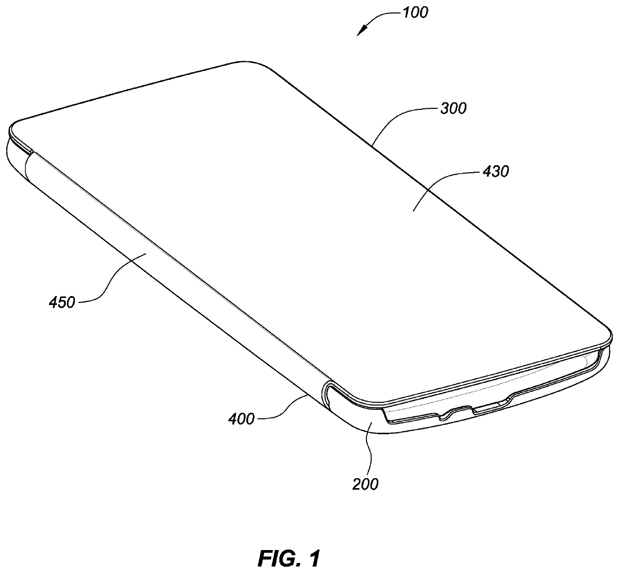
[0032]As illustrated in the accompanying drawings, the protective case 100 is generally configured to receive and protect a mobile device. The case 100 generally includes a shell component 200 comprised of multiple interlocking panels and a cover component 300 comprised of a cover panel 305 that is attached to the shell via a spine 450. The two components are in the illustrated embodiments attached to one another via a connector component 400, which is comprised of inner and outer layers 410, 430 that overlay the shell and cover panels.
[0033]The protective case 100 may be for a mobile device that is in the form of a tablet, a smart or mobile phone, an MP3 audio player, a g...
PUM
Abstract
A protective case for a portable mobile device is disclosed. The protective case comprises a shell that defines a compartment for receiving and retaining a mobile device, a cover panel, and a connector component. The shell has a main panel that includes an aperture and a subpanel that is hinged at a first side within the aperture and reversibly attached to the aperture via mechanical protrusions or detents at a second side so that it can rotatably attach and detach, or snap, into and out of the main panel. The hinge may be formed by one or more flexible layers overlaid on the shell or via mechanical swivel joint such as a pin and socket connection. A connector portion connects the cover panel to the shell and forms a flexible spine between the cover panel and the shell. The connector portion is comprised of opposing inner and outer layers that are overlaid over the internal and external facing surfaces of the shell and cover panel. The main panel of the shell is configured to receive and retain the mobile device within its compartment and may be snap-fitted over the mobile device. In operation, the case can be opened and the subpanel detached from the main panel to allow the main panel to rotate relative to the subpanel and rest on the inner surface of the cover component to provide varied viewing / operating positions to the user.
Description
CROSS-REFERENCE TO RELATED APPLICATIONS[0001]This application is a continuation of U.S. patent application Ser. No. 17 / 103,932, filed on Nov. 24, 2020, which is a divisional of U.S. patent application Ser. No. 16 / 362,233, filed on Mar. 22, 2019 and issued as U.S. Pat. No. 10,848,195 on Nov. 24, 2020, which is a continuation of U.S. patent application Ser. No. 15 / 200,372, filed on Jul. 1, 2016 and issued as U.S. Pat. No. 10,243,608 on Mar. 26, 2019, which claims the benefit of and priority to U.S. Provisional Patent Application Ser. No. 62 / 188,438, filed on Jul. 2, 2015, the entireties of which are hereby incorporated herein by reference.BACKGROUNDField of the Invention[0002]The present disclosure relates to user removable protective cases for mobile devices, and particularly lightweight folio-type cases.Description of the Related Art[0003]Mobile devices, such as smartphones, tablets, laptops, and the like are known to sustain damage from impact and from contamination as a result of ...
Claims
Application Information
Patent Timeline
Application Date:The date an application was filed.
Publication Date:The date a patent or application was officially published.
First Publication Date:The earliest publication date of a patent with the same application number.
Issue Date:Publication date of the patent grant document.
PCT Entry Date:The Entry date of PCT National Phase.
Estimated Expiry Date:The statutory expiry date of a patent right according to the Patent Law, and it is the longest term of protection that the patent right can achieve without the termination of the patent right due to other reasons(Term extension factor has been taken into account ).
Invalid Date:Actual expiry date is based on effective date or publication date of legal transaction data of invalid patent.
Patent Type & Authority Applications(United States)
