A floating sealing device for pulverized coal pyrolysis kiln

A technology of floating seals and pyrolysis kilns, which is applied in the directions of engine seals, engine components, special forms of retort, etc., can solve the problems of increased seal wear of the rotary cylinder, and achieve reliable and stable operation, reduced damage, and a firm anti-rotation structure Effect

Active Publication Date: 2017-12-12
CHINA NAT HEAVY MACHINERY RES INSTCO
View PDF4 Cites 0 Cited by
  • Summary
  • Abstract
  • Description
  • Claims
  • Application Information

AI Technical Summary

Problems solved by technology

[0003] In order to overcome the problem of increased seal wear caused by the swaying and swinging of the rotary cylinder, the present invention proposes a floating sealing device for pulverized coal pyrolysis kiln

Method used


Image

  • A floating sealing device for pulverized coal pyrolysis kiln
  • A floating sealing device for pulverized coal pyrolysis kiln
  • A floating sealing device for pulverized coal pyrolysis kiln

Examples


Embodiment 1

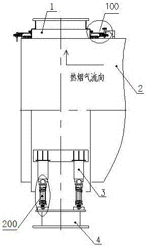
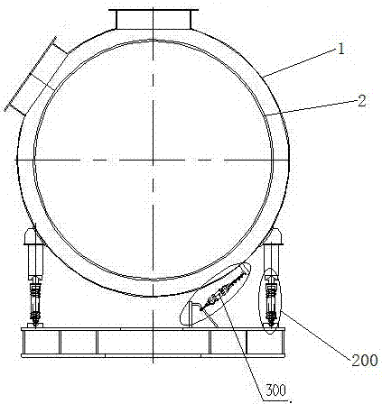
[0030] In order to overcome the problem of aggravated seal wear caused by the swaying and swinging of the rotary cylinder, this embodiment proposes a floating sealing device for pulverized coal pyrolysis kiln, such as figure 1 and figure 2 As shown, it includes a rotating cylinder 2 and a floating cover 1 set outside one end of the rotating cylinder 2. The lower part of the floating cover 1 is connected to the frame 4 through support legs 3. The two ends of the floating cover 1 are connected to the rotating A sealing structure 100 is provided between the cylinders 2 , a floating support structure 200 is provided between the support legs 3 and the frame 4 , and an anti-rotation structure 300 is provided between the floating cover 1 and the frame 4 .

[0031] The working principle of the present invention is as follows:

[0032] The floating cover 1 is set on the outside of the end of the rotating cylinder 2. Six air outlet holes are distributed radially on the cylinder of the...

Embodiment 2

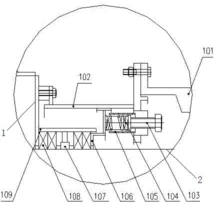
[0035] Such as image 3 As shown, the sealing structure 100 includes an adjustment mechanism 101, an intermediate spacer 102, a guide sleeve 105, a moving ring 106, an oil storage ring 107, a packing 108 and a packing sleeve 109, and the intermediate spacer 102 is set on the rotating On the cylinder body 2, one end of the middle spacer 102 is fixed to the floating cover 1 by bolts, the other end is connected with an adjustment mechanism, the lower end of the middle spacer 102 is provided with a moving ring 106, and the middle spacer 102 is connected to the lower part of one end of the adjustment mechanism A guide sleeve 105 is welded, and a spring one 104 is arranged inside the guide sleeve 105, one end of the spring one 104 is connected to the end of the bolt 103, the other end of the spring one 104 is in contact with the upper side of the moving ring 106, and the middle spacer 102 A packing sleeve 109 is arranged under one end fixed to the floating cover body 1, and the pack...

Embodiment 3

[0039] Such as Figure 4As shown, the floating support structure 200 includes a spherical base 201, a guide shaft 203 and a support plate 206 sequentially connected from top to bottom, the support plate 206 is welded on the frame 4, and the outside of the guide shaft 203 is sleeved from top to bottom Have spring two 202, pressing plate 204 and nut one 205.

[0040] Preferably, the lower end of the guide shaft 203 is spherical and can float on the floating support plate 206 .

[0041] Further, there are four supporting legs 3 , which are welded to the floating cover 1 . The lower part of the supporting legs 3 is a concave spherical surface.

[0042] The self-weight of the floating cover body 1 and the movement and deflection of the rotating cylinder 2 are transmitted to the spherical base 201 through the support legs 3, compensated and adapted by the compression spring 202, and the nut 1 205 overcomes the floating through the compression plate 204 and the compression spring 20...


PUM


Abstract

The invention provides a floating sealing device of a pulverized coal pyrolysis kiln. The floating sealing device comprises a rotary barrel body and a floating cover body arranged at the outer side of one end of the rotary barrel body in a sleeved mode, wherein the lower part of the floating cover body is connected onto a rack through supporting legs; sealing structures are arranged between the two ends of the floating cover body and the rotary barrel body; floating supporting structures are arranged between the supporting legs and the rack; and an anti-rotating structure is arranged between the floating cover body and the rack. The floating sealing device provided by the invention solves the problem that sealing wear caused by shifting and swinging of the rotary barrel body is intensified, breaks through a technological difficulty of the pyrolysis kiln, and guarantees reliable and stable operation of equipment.

Description

technical field [0001] The invention relates to the technical field of rotary kiln sealing, in particular to a floating sealing device for pulverized coal pyrolysis kiln. Background technique [0002] At present, in the rotary kiln method used in the chemical industry and building materials industry, the kiln head and kiln tail are mostly sealed with fish scale plate structure, or composite seal. Due to the dynamic and static seal between the rotary body and the fixed cover, the seal wear is intensified due to the movement and swing of the rotary cylinder, so the traditional seal is not reliable, and a sealing structure with a fixed cover that can float is needed to extend Seal life. At present, there is no floating structure for this kind of sealing occasion, and the floating structure used in the mature flexible transmission technology can be used for reference. Contents of the invention [0003] In order to overcome the problem of increased seal wear caused by the swa...

Claims


Application Information

Patent Timeline
Patent Type & Authority Patents(China)
IPC IPC(8): F16J15/16C10B53/04
CPCC10B53/04F16J15/162
Inventor 王广收赵玉良葛延
Owner CHINA NAT HEAVY MACHINERY RES INSTCO
Why Eureka
Try Eureka