
Anti-twist structure of voice coil motor

a voice coil motor and anti-twist technology, applied in the field of optical lenses, can solve the problems of clogging and pollution problems, lens may still be subject to external forces or component forces, lens may not be moved upward/down, etc., and achieve the effect of limiting the elevation of the lens and quickly moving

Pending Publication Date: 2021-09-02
KUNSHAN LIANTAO ELECTRONICS CO LTD
View PDF2 Cites 0 Cited by
  • Summary
  • Abstract
  • Description
  • Claims
  • Application Information

AI Technical Summary

Benefits of technology

The present invention relates to an anti-twist structure for lens modules, which includes a lens housing and yoke member. The lens housing has a first protrusion and the yoke member has a stepped structure on its upper portion. This design prevents interference between the lens housing and yoke member when the lens housing reaches its maximum deflectable angle. The anti-twist structure is made of elastic sheets that allow quick movement of the lens housing back to its original position when subjected to a small-angle deflection, ensuring the service life of the overall lens module.

Problems solved by technology

However, when the lens is moving, such as when the lens is moving forward / backward in the Z direction, the lens may still be subjected to external forces or component forces caused by its own weight in other directions different from the Z direction.
When the lens housing is excessively deflected, the entire lens module may be stuck and cannot be moved upward / downward.
Though a slight deflection will not affect the elevating function of the lens module, in a long-term perspective, the friction between the lens housing and the yoke member due to the deflection of the lens housing will produce abrasion debris, which can easily cause clogging and pollution problems, and even affect the operation of the lens module or the quality of image-capturing.
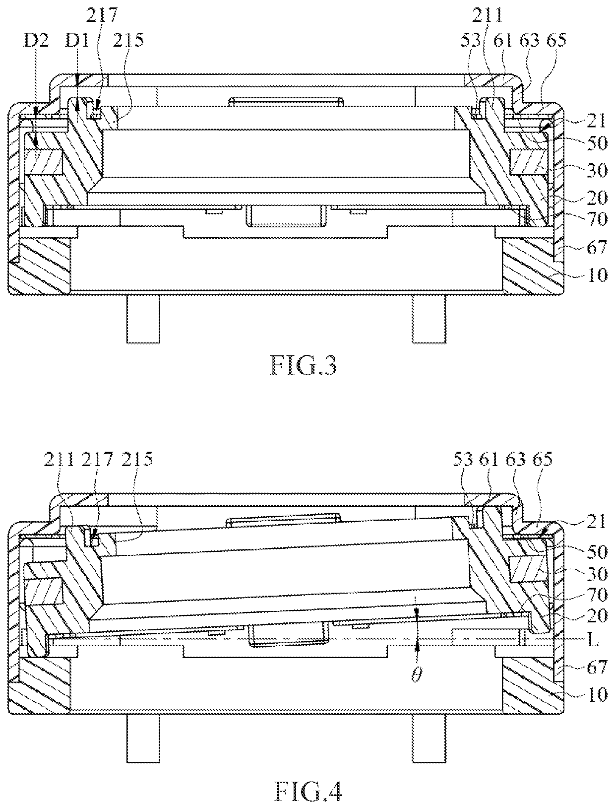
Therefore, when the lens housing deflects to the maximum value of the deflectable angle θ, the first margin wall abuts against the second wall and / or the first protrusion abuts against the first wall, so that the lens housing and the yoke member interfere with each other.

Method used


Image

  • Anti-twist structure of voice coil motor
  • Anti-twist structure of voice coil motor
  • Anti-twist structure of voice coil motor

Examples


Embodiment Construction

[0026]Hereinafter, the principle of structures and the principle of operation of the present disclosure will be described more fully with reference to the accompanying drawings.

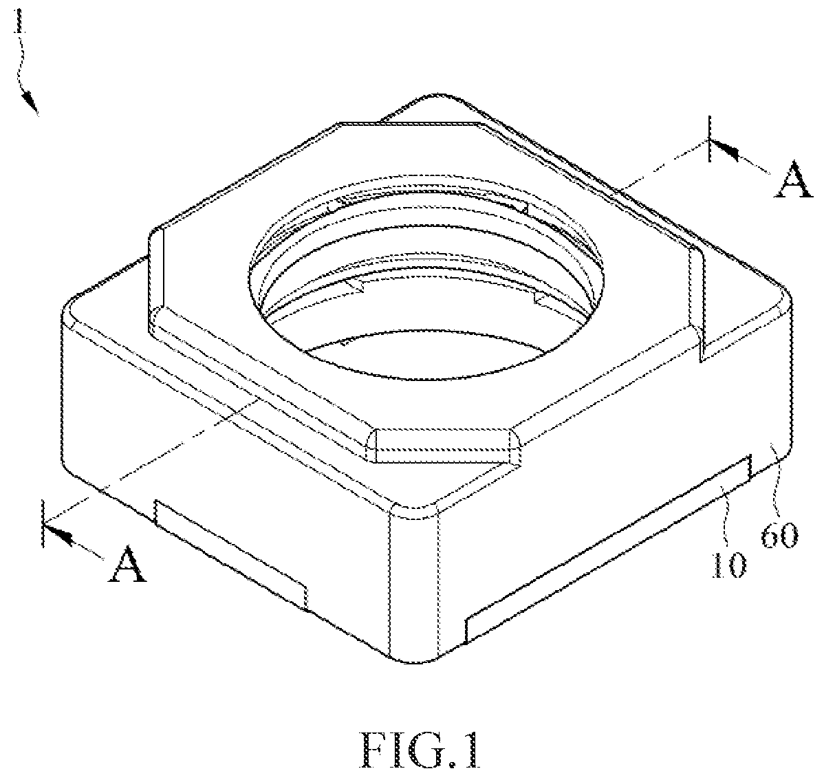
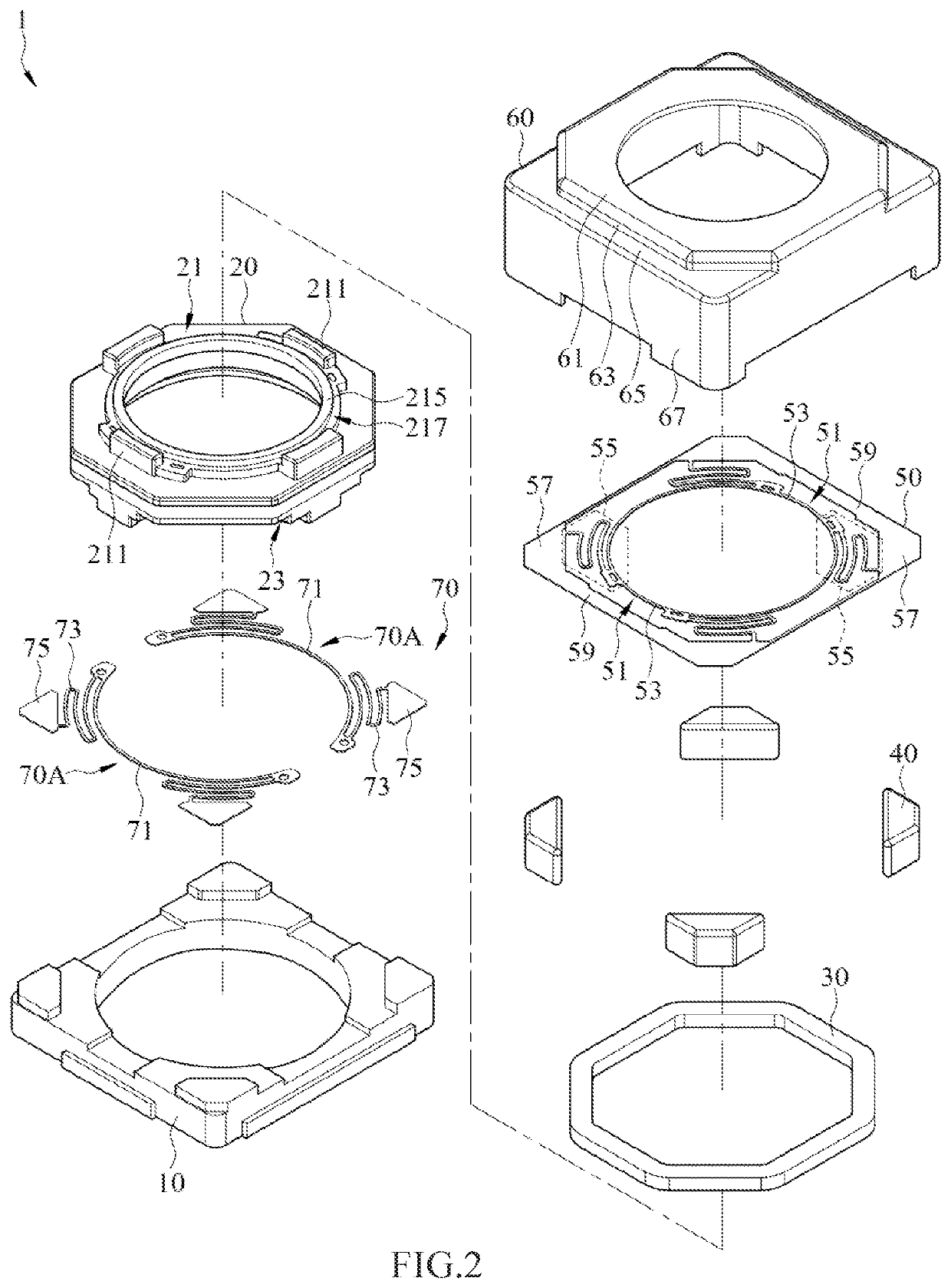
[0027]FIG. 1 illustrates a schematic perspective view of an anti-twist structure 1 of voice coil motor according to the exemplary embodiment of the present disclosure. FIG. 2 illustrates a schematic exploded view of the anti-twist structure 1 of voice coil motor according to the exemplary embodiment of the present disclosure. FIG. 3 illustrates a schematic cross-sectional view of the anti-twist structure 1 of voice coil motor according to the exemplary embodiment of the present disclosure. As shown in FIG. 1 to FIG. 3, the anti-twist structure 1 of voice coil motor includes a base 10, a lens housing 20, a voice coil 30, a magnet 40, a first elastic sheet 50, a yoke member 60, and a second elastic sheet 70. The lens housing 20 is connected to the base 10. The lens housing 20 a first margin wall 21 and a second...


PUM


Abstract

An anti-twist structure of a voice coil motor includes a base, a lens housing, a first elastic sheet, a second elastic sheet, a magnet, and a yoke member. The lens housing has first margin wall and a second margin wall, and a first protrusion extends from the first margin wall. The height of the second protrusion is lower than the height of the first protrusion. The yoke member has a first wall, a connection wall, a second wall, and a side wall. The first wall is disposed above the first protrusion, and the second wall is disposed above the second protrusion. The lens housing has a deflectable angle relative to a horizontal reference line. When the lens housing deflects to a maximum value of the deflectable angle, the first margin wall abuts against the second wall and / or the first protrusion abuts against the first wall.

Description

CROSS-REFERENCE TO RELATED APPLICATION[0001]This non-provisional application claims priority under 35 U.S.C. § 119(a) to Patent Application No. 202023067751.5 filed in China, P.R.C. on Dec. 18, 2020, the entire contents of which are hereby incorporated by reference.BACKGROUNDTechnical Field[0002]The present disclosure relates to a field of optical lenses, and more specifically relates to an anti-twist structure of voice coil motor.Related Art[0003]Almost all current smart mobile devices are equipped with lens modules. Miniaturizing the lens module and driving the lens of the lens module to elevate or to zoom in / out are mainly achieved through a voice coil motor.[0004]A voice coil motor generally includes a lens housing, a voice coil, a magnet, and a yoke member. Through receiving electrical signals by the voice coil, the voice coil interacts with the magnet, thereby driving the lens to move. However, when the lens is moving, such as when the lens is moving forward / backward in the Z ...

Claims


Application Information

Patent Timeline
Patent Type & Authority Applications(United States)
IPC IPC(8): H04N5/225H04N5/232H02K41/035G02B7/09G02B7/08G03B3/10
CPCH04N5/2254H04N5/2257H04N5/23296G03B2205/0069G02B7/09G02B7/08G03B3/10H02K41/0354H02K41/0356G03B30/00G03B2205/0023H04N23/57H04N23/55H04N23/69
Inventor HUANG, WEN-YENLIN, MENG-TINGWU, FU-YUANHSU, SHANG-YUMA, BING-BINGDU, JIE
Owner KUNSHAN LIANTAO ELECTRONICS CO LTD
Learn More