
Caster comprising a running wheel

Active Publication Date: 2021-09-09
TENTE
View PDF0 Cites 2 Cited by
  • Summary
  • Abstract
  • Description
  • Claims
  • Application Information

AI Technical Summary

Benefits of technology

The patent describes a braking device for bicycles that has improved performance and flexibility. It uses a roller bearing to reduce the switching forces and a fixed and elastically movable part to ensure consistent operation. The braking device can also be displaced as a unit to its braking end position, allowing for easier adjustment and preventing damage to the braking parts. Overall, this braking device provides better performance and flexibility for bicycles.

Problems solved by technology

The first problem is solved in that the tappets are arranged next to one another transverse to a vertical direction in a normal operating position of the caster, and extend next to one another in the vertical direction, and that the trip cam has two cam surfaces which are each assigned to one tappet, and that the cam surfaces are designed differently from each other.

Method used


Image

  • Caster comprising a running wheel
  • Caster comprising a running wheel
  • Caster comprising a running wheel

Examples


Embodiment Construction

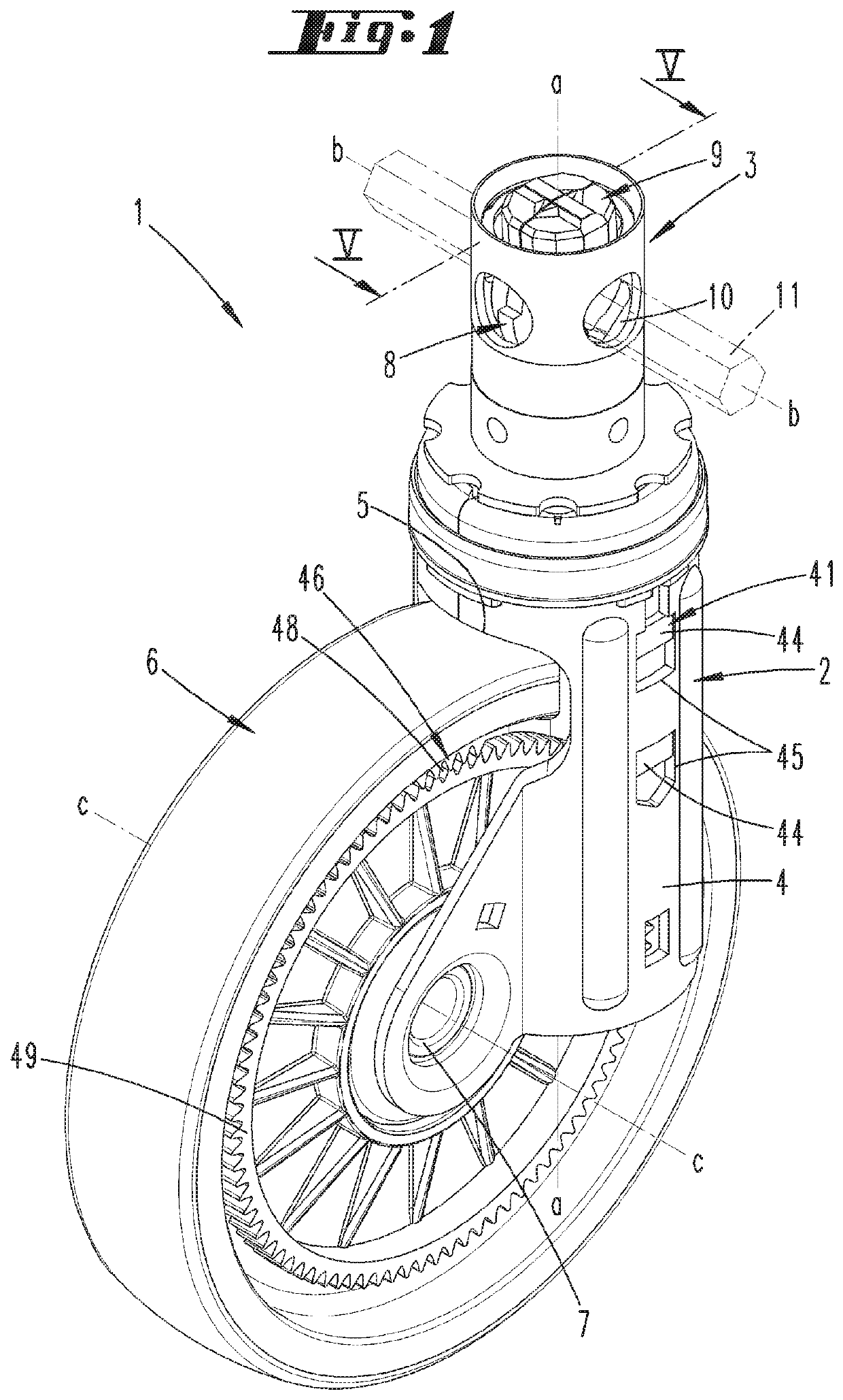
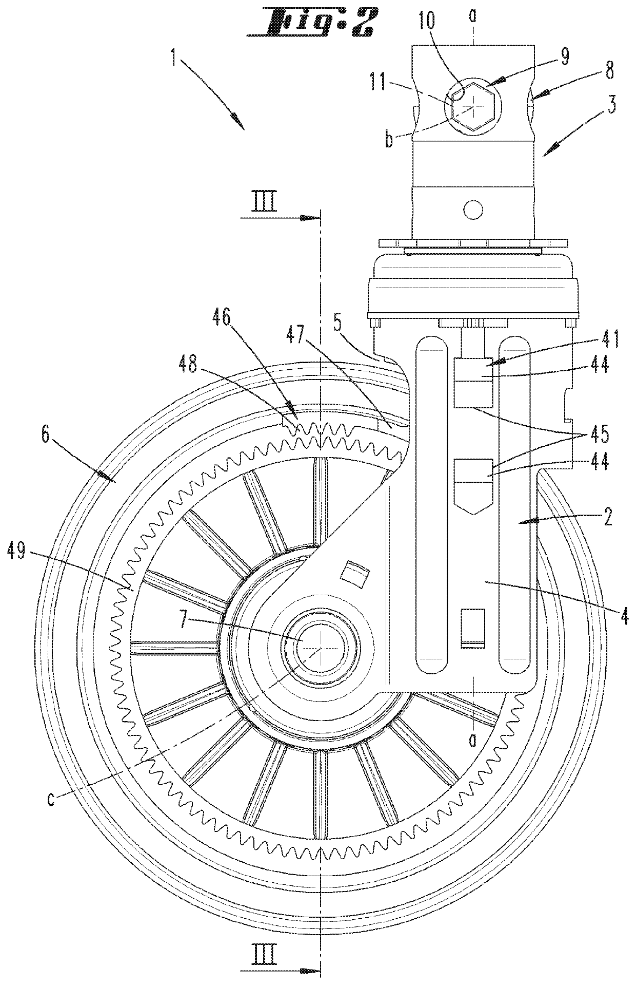
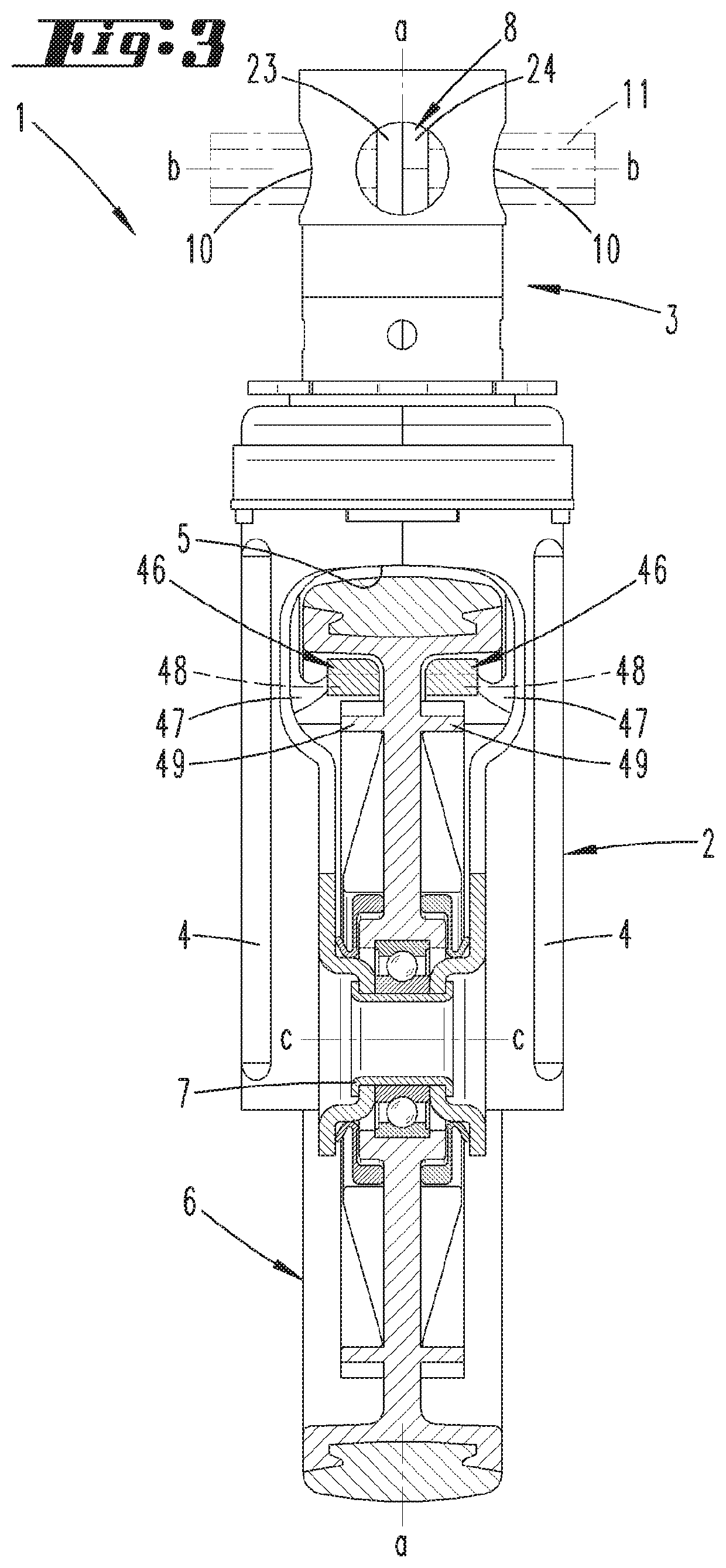
[0048]A caster comprising a fork 2, from which a cylindrically configured assembly journal 3 projects vertically surrounding a pivot axis a, is shown and described initially with reference to FIG. 1.

[0049]Fork 2 flanks, with its fork legs 4 arranged preferably congruently opposite one another, a running wheel 6 mounted in a fork cavity 5. A hollow axle 7, which penetrates running wheel 6 centrally and is mounted on the respective end sides on fork legs 4, functions for mounting running wheel 6. The wheel axle c runs transversely to pivot axis a.

[0050]Caster 1 as depicted may be positioned, e.g., on a hospital bed or the like. The fixing is then carried out in the usual way and is therefore not described here in any detail.

[0051]A trip cam 8 is provided in assembly journal 3 and arranged to move pivotably about an actuating axis b. Actuating axis b hereby extends in the exemplary embodiment shown perpendicularly and correspondingly transversely to pivot axis a of caster 1, thus corre...


PUM


Abstract

A caster includes a running wheel, a fork and an assembly journal, wherein the fork is pivotable in relation to the assembly journal and a braking device is arranged in the fork and can be displaced into the braking position via a tappet actuated by a trip cam. A direction lock can be set without a braking action on the running wheel. Two tappets are movable independently of each other, wherein only the direction lock without a braking action can be set via one of the tappets. Another caster includes a running wheel, a fork and an assembly journal, wherein a braking device is provided in the fork and can be displaced into the braking position via a trip cam. The braking device has a first braking part for friction-locking action on the running wheel and a second braking part for the interlocking lock of the running wheel.

Description

TECHNICAL FIELD[0001]The invention initially relates to a caster comprising a running wheel, a fork, and an assembly journal, wherein the fork is pivotable in relation to the assembly journal, and a braking device is furthermore arranged in the fork which is displaceable into a braking position via a tappet actuated by a trip cam, wherein a direction lock may be set without a braking action on the running wheel, and two tappets are provided which are movable independently of each other, wherein only the direction lock without a braking action is able to be set via one of the tappets.[0002]Furthermore, the invention relates to a caster comprising a running wheel, a fork, and an assembly journal, wherein a braking device is provided in the fork which is preferably displaceable into the braking position via a trip cam, wherein the braking device has a first braking part for friction-locking action on the running wheel.PRIOR ART[0003]Casters of the type in question are known. These are ...

Claims


Application Information

Patent Timeline
Patent Type & Authority Applications(United States)
IPC IPC(8): B60B33/00B60B33/02
CPCB60B33/0049B60B33/0068B60B2200/242B60B33/021B60B33/0086B60B33/0057B60B33/0081B60B33/025B60B2900/115B60B2900/531
Inventor HARTKOPF, HORST
Owner TENTE
Learn More